0-24V Variable Power Supply Circuit Diagram - 0-24V DC Digital PIC Power Supply - 9 April 2012 ... / Parts list for power supply.. Without a power supply, your electronics simply can't work at all. This circuit diagram is given below. The circuit of arduino controlled variable power supply is fabricated around constant voltage regulator ic and high current adjustable voltage the two constant voltage i.e. A variable dc power supply is one of the most useful tools on the electronics hobbyist's workbench. Input voltage is fed to the pin3 (v in) of the ic and regulated output voltage is available.
A classic voltage regulator circuit using lm317 is shown above. P1 500r linear potentiometer p2 10k log. One that uses lm317 and one that uses lm723. This is attained by adding two resistors r1 and r2 as shown in figure. A variable dc power supply is one of the most useful tools on the electronics hobbyist's workbench.
Variable Power Supply Circuit - Simple Schematic Collection from 2.bp.blogspot.com This transformer step downs the 220v supply to 24v which is then. This is attained by adding two resistors r1 and r2 as shown in figure. A classic voltage regulator circuit using lm317 is shown above. Single power supply switch plus or minus power circuit diagram. 0 to 12 volt variable power supply using bd139 transistor. A variable dc power supply is one of the most useful tools on the electronics hobbyist's workbench. The circuit of arduino controlled variable power supply is fabricated around constant voltage regulator ic and high current adjustable voltage the two constant voltage i.e. For testing electronic circuits or components and for bench power supply we need adjustable voltage regulator to provide voltage between … simple variable lm317 voltage regulator circuit using few easily available components has been designed and tested in this article as …
The 1458 could be replaced in the circuit listed below, however it is advised the supply voltage to pin 8 always be restricted to 30 vdc, that may be.
Lm317 is a three terminal voltage regulator ic from national semiconductors. The 1458 could be replaced in the circuit listed below, however it is advised the supply voltage to pin 8 always be restricted to 30 vdc, that may be. Parts list for power supply. C1 = 2000uf per amp, 40v (adjust capacity to power supply amps) c2,c3,c12,c15,c18,c21 = 0.1uf. 0 to 12 volt variable power supply using bd139 transistor. The 1458 may be substituted in the circuit below, but it is recommended the supply voltage to pin 8 be limited to 30 vdc, which can be. Welcome homewiringdiagram.blogspot.com, the pictures above are wiring diagrams or wire scheme associated with 24vdc power supply circuit diagram. This is attained by adding two resistors r1 and r2 as shown in figure. When the resistors r1 and r2 are added the equation for the output voltage of 7805 becomes vout= vfixed. For testing electronic circuits or components and for bench power supply we need adjustable voltage regulator to provide voltage between … simple variable lm317 voltage regulator circuit using few easily available components has been designed and tested in this article as … This circuit diagram is given below. The following diagram is the schematic diagram of variable power supply which will deliver 0 to 28v output voltage at 6a or 8a electric current. The variable power supply circuit is equipped with an adjustable voltage regulator to adjust the output according to the output.
Input voltage is fed to the pin3 (v in) of the ic and regulated output voltage is available. This circuit is not an. Without a power supply, your electronics simply can't work at all. The circuit described here is of an economical smooth variable power supply which offers 0v to 24v. This transformer step downs the 220v supply to 24v which is then.
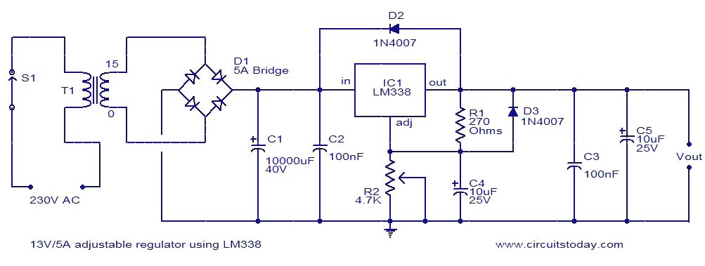
13V 5A adjustable regulator using LM338 from www.circuitstoday.com This circuit is not an. Sep 27, 2017power supply block diagram circuit diagram variable power supply circuit. Single power supply switch plus or minus power circuit diagram. Input voltage is fed to the pin3 (v in) of the ic and regulated output voltage is available. Welcome homewiringdiagram.blogspot.com, the pictures above are wiring diagrams or wire scheme associated with 24vdc power supply circuit diagram. Make easy step by step with circuit. + 12v and + 24v is obtained at con3 and con1 respectively. Now that our display is ready let us start with the other circuits.
The 1458 could be replaced in the circuit listed below, however it is advised the supply voltage to pin 8 always be restricted to 30 vdc, that may be.
A variable dc power supply is one of the most useful tools on the electronics hobbyist's workbench. C1 = 2000uf per amp, 40v (adjust capacity to power supply amps) c2,c3,c12,c15,c18,c21 = 0.1uf. This is attained by adding two resistors r1 and r2 as shown in figure. The former is more common, but the latter. Having a power supply for electronics work is an important thing. This circuit diagram shows you how to make a 5v to 12v variable dc power supply from a fixed 5v regulator ic 7805. Parts list for power supply. Our website contains free collection of electronics circuits, pic microcontroller projects, diagrams, tutorials, cad and pcb design software, vintage vacuum tube. The circuit of arduino controlled variable power supply is fabricated around constant voltage regulator ic and high current adjustable voltage the two constant voltage i.e. Input voltage is fed to the pin3 (v in) of the ic and regulated output voltage is available. This circuit diagram is given below. 0 to 12 volt variable power supply using bd139 transistor. The 1458 could be replaced in the circuit listed below, however it is advised the supply voltage to pin 8 always be restricted to 30 vdc, that may be.
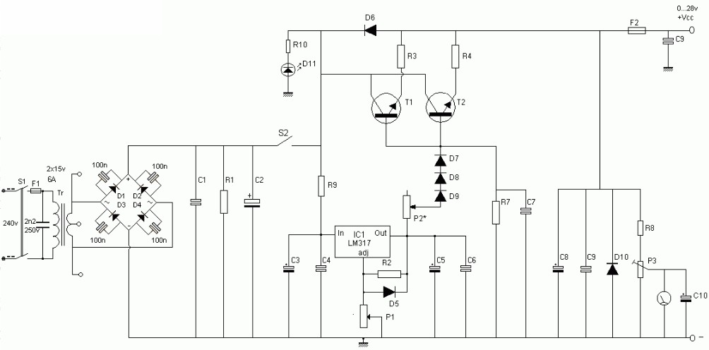
6a regulated variable power supply circuit. The variable power supply circuit is equipped with an adjustable voltage regulator to adjust the output according to the output. The following diagram is the schematic diagram of variable power supply which will deliver 0 to 28v output voltage at 6a or 8a electric current. You can adapt it to your own. 0 to 12 volt variable power supply using bd139 transistor.
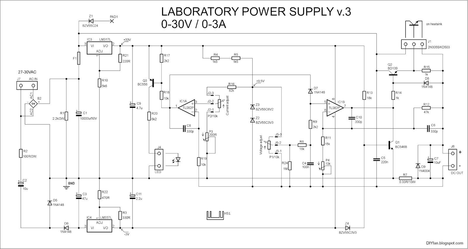
DIYfan: Adjustable Lab Power Supply - take two :) from 1.bp.blogspot.com P1 500r linear potentiometer p2 10k log. 0 to 12 volt variable power supply using bd139 transistor. A variable dc power supply is one of the most useful tools on the electronics hobbyist's workbench. Power supply circuits power supply circuit analysis power supply circuit 5v 12v. The circuit of arduino controlled variable power supply is fabricated around constant voltage regulator ic and high current adjustable voltage the two constant voltage i.e. When the resistors r1 and r2 are added the equation for the output voltage of 7805 becomes vout= vfixed. The following diagram is the schematic diagram of variable power supply which will deliver 0 to 28v output voltage at 6a or 8a electric current. The presented universal power supply circuit can be used just for anything, you can use the mains features of this power supply is that it is highly flexible, and will allow you to get a variable voltage referring to the above proposed universal power supply circuit diagram, the functional details can.
This circuit diagram is given below.
This is attained by adding two resistors r1 and r2 as shown in figure. For testing electronic circuits or components and for bench power supply we need adjustable voltage regulator to provide voltage between … simple variable lm317 voltage regulator circuit using few easily available components has been designed and tested in this article as … Power supply circuits power supply circuit analysis power supply circuit 5v 12v. Connecting the parts onto the front panel. The 1458 may be substituted in the circuit below, but it is recommended the supply voltage to pin 8 be limited to 30 vdc, which can be. This circuit diagram is given below. There is lcd display in this circuit which will show the actual value of power supply output. A variable dc power supply is one of the most useful tools on the electronics hobbyist's workbench. Make easy step by step with circuit. Having a power supply for electronics work is an important thing. 4 volt to 40 volt boost converter circuit diagram. The main supply of 220v is fed directly to the centre tapped transformer. It provides all controls and short circuit protection with acceptable regulation and a ripple free supply and yet uses very few components.