Home
› Solar Charge Controller Diagram / Buy Bluetooth MPPT Solar Charge Controller for RV online : It's not designed to deal with shore power in any voltage.
Solar Charge Controller Diagram / Buy Bluetooth MPPT Solar Charge Controller for RV online : It's not designed to deal with shore power in any voltage.
Solar Charge Controller Diagram / Buy Bluetooth MPPT Solar Charge Controller for RV online : It's not designed to deal with shore power in any voltage.. A few things to note in the diagram: When charging from solar, the solar panels & charge controller charge the batteries. Most 12 volt panels put out about 16 to 20 volts, so if there is no regulation the batteries will be damaged from overcharging. • wiring solar panels in parallel. Solar charge controller wiring diagram | pwm installation pwm solar charge controller installation.
#howtomakesolarchargecontroller #solarpannel #chargecontrollerthis video will show you how to build a home made solar charge controller featuring :over volta. Battery and inverter are connected to the battery terminals (positive & negative) of the charge controller. The switch (transistor) is open until the battery reaches the absorption charge voltage. When the solar panel charges the battery up to the desired full voltage, the shunt circuit connects a resistive load across the battery to absorb the excess power from the solar panel. The batteries are connected to the dc fuse block allowing use of the 12v devices around the camper.
Simple 10 Amp Solar Charge Controller Circuit Diagram from 2.bp.blogspot.com This diagram also shows how to wire multiple solar arrays through multiple charge controllers into the lynx distributor. Final design finally i relented. #howtomakesolarchargecontroller #solarpannel #chargecontrollerthis video will show you how to build a home made solar charge controller featuring :over volta. Most solar controllers are single output so charge only one battery bank. How many do you need? I want to design mppt charge controller for 50w,12v solar pannel…and also i want to make the output voltage from the charger controller should be varied based upon our requriment…can you please send me the circuit diagram… and the ratting of the components that i have to use sir…. Solar panel kits renogy 300w solar kit (pwm charge controller) windynation 100w solar kit (pwm charge controller and battery included) Solar charge controller wiring diagram | pwm installation pwm solar charge controller installation.
Mppt solar charge controller block diagram
The first solar charge controller schematic below (figure 1) illustrates how a solar charge controller is connected to power a direct current (dc) load, and the second one (figure 2) pertains to an alternating current (ac) load. The batteries are connected to the dc fuse block allowing use of the 12v devices around the camper. As you see in the connection diagram at first, the solar panel is connected to the solar charge controller and then a 24v battery is connected to the charge controller. The complete installation diagram with main supply, solar panels, inverter/ups and load connection. A pwm charge controller is a low cost, budget friendly option. Please sir can you make me a 12v, 28.8ah lithium ion battery,automatic charge controller using solar panel as a supply, which is 17v at 4.5a at max sun light. A solar panel is a collection of solar cells. Final design finally i relented. This diagram is for users requiring extensive power demands through 120v/240v split phase at up to 3000w per leg. The maximum power point tracking (mppt) system is an electronic system that enables the photovoltaic panel to output more power by adjusting the working state of the electrical module. The dc power generated by the solar panel can be efficiently stored in a battery. Diy automatic solar charge controller: When charging from solar, the solar panels & charge controller charge the batteries.
The switch (transistor) is open until the battery reaches the absorption charge voltage. This diagram also shows how to wire multiple solar arrays through multiple charge controllers into the lynx distributor. The dc power generated by the solar panel can be efficiently stored in a battery. The complete installation diagram with main supply, solar panels, inverter/ups and load connection. The solar panel uses ohmic material for interconnections as well as the external terminals.
12v Solar Charge Controller Wiring Diagram | Wiring Library from www.seekic.com This diagram is for users requiring extensive power demands through 120v/240v split phase at up to 3000w per leg. There's 2 types of solar charge controller: A solar panel is a collection of solar cells. A few things to note in the diagram: It's an automatic switching circuit that used to control the charging of a battery from solar panels or any other source. You will need to choose just one charge controller for your entire system. It has several advantages over the earlier charge controller. The batteries are connected to the dc fuse block allowing use of the 12v devices around the camper.
In the diagram the auto 12 volts, 24 volts, 48 volts pwm (pulse width modulation controller) solar charge controller wiring shown.
Battery and inverter are connected to the battery terminals (positive & negative) of the charge controller. The mppt controller is more sophisticated and more expensive. You will need to choose just one charge controller for your entire system. The solar panel converts solar energy into electrical energy. The switch (transistor) is open until the battery reaches the absorption charge voltage. It's a 555 based simple circui… During shading/night (when there is no generating power from solar panels) the battery stored energy will be used as a backup power and it. The maximum power point tracking (mppt) system is an electronic system that enables the photovoltaic panel to output more power by adjusting the working state of the electrical module. Then the switch starts to open and close rapidly (hundreds of time per second) to reduce the current and. This diagram is for users requiring extensive power demands through 120v/240v split phase at up to 3000w per leg. This diagram also features full system monitoring through the victron gx line of devices. Mppt solar charge controller block diagram It regulates the voltage and current coming from the solar panels going to the battery.
You will likely need to purchase a battery, inverter, fuses and wires* separately. When the solar panel charges the battery up to the desired full voltage, the shunt circuit connects a resistive load across the battery to absorb the excess power from the solar panel. This diagram is for users requiring extensive power demands through 120v/240v split phase at up to 3000w per leg. During shading/night (when there is no generating power from solar panels) the battery stored energy will be used as a backup power and it. The complete installation diagram with main supply, solar panels, inverter/ups and load connection.
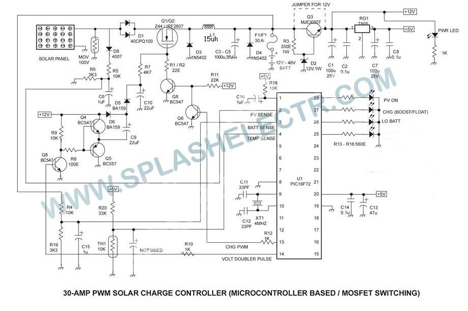
SPLASH ELECTR: PWM SOLAR CHARGE CONTROLLER CIRCUIT AND TECHNOLOGY TRANSFER from 3.bp.blogspot.com The first solar charge controller schematic below (figure 1) illustrates how a solar charge controller is connected to power a direct current (dc) load, and the second one (figure 2) pertains to an alternating current (ac) load. This diagram is for users requiring extensive power demands through 120v/240v split phase at up to 3000w per leg. The following solar panel wiring diagram shows that an 120w, 12v solar panel is directly connected to the 12v charge controller. You will need to choose just one charge controller for your entire system. The batteries are connected to the dc fuse block allowing use of the 12v devices around the camper. A few things to note in the diagram: The charge controller should be able to have over charge protection and low battery cut off and the circuit should be simple to do for beginner without ic or micro controller. During shading/night (when there is no generating power from solar panels) the battery stored energy will be used as a backup power and it.
Solar charge controllers regulate the current from the panels to a safe level so it can charge the batteries.
This diagram is for users requiring extensive power demands through 120v/240v split phase at up to 3000w per leg. A few things to note in the diagram: Second, then connect your solar panel to your charge. The first solar charge controller schematic below (figure 1) illustrates how a solar charge controller is connected to power a direct current (dc) load, and the second one (figure 2) pertains to an alternating current (ac) load. Solar panel kits renogy 300w solar kit (pwm charge controller) windynation 100w solar kit (pwm charge controller and battery included) The complete installation diagram with main supply, solar panels, inverter/ups and load connection. Mppt charge controller simple guide what is maximum power point tracking. This diagram also features full system monitoring through the victron gx line of devices. Battery and inverter are connected to the battery terminals (positive & negative) of the charge controller. The charge controller monitors and regulates the entire system, thus it is the brain. Dc load is also connected to the dc output terminal of the charge controller. The following wiring diagram shows that the two 12v, 10a, 120w solar panels connected in parallel will charge the two 12v, 100ah parallel connected batteries as well as power up the ac load through batteries and inverter during the day in normal sunshine. It's an automatic switching circuit that used to control the charging of a battery from solar panels or any other source.