Home
› Wiring Diagram Plc Ladder Diagram - B Design A B R Plc Ladder Logic Program And Prepare Chegg Com : Note the number 1 on the wire between the switch and the lamp.
Wiring Diagram Plc Ladder Diagram - B Design A B R Plc Ladder Logic Program And Prepare Chegg Com : Note the number 1 on the wire between the switch and the lamp.
Wiring Diagram Plc Ladder Diagram - B Design A B R Plc Ladder Logic Program And Prepare Chegg Com : Note the number 1 on the wire between the switch and the lamp.. Yamaha blaster wiring diagram free download. Ladder diagrams describe programs in graphical form, used in plc programming. Block diagram of plc with explanation. Importance of wire numbers in a circuit. Introduction to plc ladder diagrams | free plc tutorials feb 10, 2016a very commonly used method of programming plcs is based on the use electrical wiring diagrams of the plc panel.
The plc simply does not plug into a wall socket in an industrial setting. Motor control circuits ladder logic electronics textbook. How to convert a basic wiring. Learn the programmable logic controllers starting with a simple example to the complex level logic.plc courses. Importance of wire numbers in a circuit.
Ladder Logic Basics Ladder Logic World from ladderlogicworld.com A ladder diagram is read from left to right and from top to bottom. The 1st feel you have to do is physically open up the welding equipment or godown wiring. Ladder logic (also known as ladder diagram or ld) is a programming language used to program a plc ( programmable logic controller ). When you are finished, your program will look very let's start converting our simple wiring diagram to the plc program in a step by step format. I'm using the siemens tia portal as the plc programming software. Plc wiring diagram p pump m motor t92s11d22. This chapter introduces basic and advanced concepts of ladder logic, which is the most. Basics of plc ladder programming.
Assuming there is absolutely no outdated spool of mig godown wiring plc ladder diagram around the mig welder.
A wiring diagram is a simplified conventional photographic representation of an electric circuit. Single phase induction motor direction control using plc. In drawing ladder diagrams the names of the associated variable or addresses of each element are appended to its symbol. Ladder logic in programmable logic controllers plcs. We can redraw this diagram in a different way, using two vertical lines to represent the input power rails and stringing the. Now that you are familiar with the wiring diagram, let's program it in ladder logic now. Introduction to plc ladder diagrams | free plc tutorials feb 10, 2016a very commonly used method of programming plcs is based on the use electrical wiring diagrams of the plc panel. This chapter introduces basic and advanced concepts of ladder logic, which is the most. Plc wiring diagram p pump m motor t92s11d22. When you are finished, your program will look very let's start converting our simple wiring diagram to the plc program in a step by step format. Ladder diagram program get rid of wiring diagram problem. In the ladder diagram there are two vertical lines where the left vertical line is connected to the positive voltage. The figure shows the scanning motion employed by the plc.
Related posts of plc wiring diagram 133 best plc programming images in 2016 plc programming ladder. How to convert a basic wiring. A program in ladder diagram notation is a circuit diagram that emulates circuits of relay logic hardware. As an introduction to ladder diagrams, consider the simple wiring diagram for an electrical circuit in figure 1.1a. Ladder logic (also known as ladder diagram or ld) is a programming language used to program a plc ( programmable logic controller ).
Plc Conveyor Motor Ladder Logic Conveyor Belt Control Using Plc from instrumentationtools.com As an introduction to ladder diagrams, consider the simple wiring diagram for an electrical circuit in figure 1.1a. Introduction to plc ladder diagrams | free plc tutorials feb 10, 2016a very commonly used method of programming plcs is based on the use electrical wiring diagrams of the plc panel. Plc wiring diagram p pump m motor t92s11d22. Ladder logic is made out of rungs of logic, forming what. A wiring diagram is an electrical print that shows connections of all components in a piece of equipment.a schematic diagram is a type of drawing that illustrates the electrical connections and functions of specific circuit arrangements with graphic symbols.a ladder diagram is a diagram that. The examples in this chapter use two simple instructions to help you learn how to write ladder diagram logic. A program in ladder diagram notation is a circuit diagram that emulates circuits of relay logic hardware. Ladder diagram program get rid of wiring diagram problem.
As an introduction to ladder diagrams, consider the simple wiring diagram for an electrical circuit in figure 1.1a.
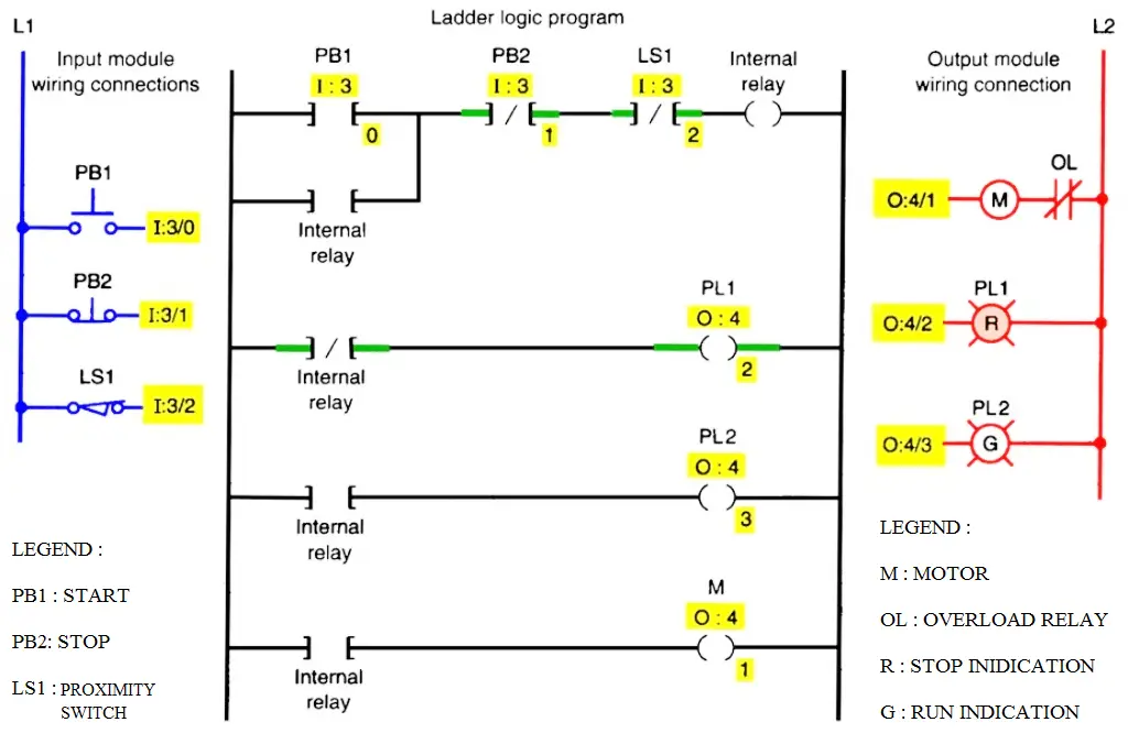
Motor control circuits ladder logic electronics textbook. Single phase induction motor direction control using plc. Yamaha blaster wiring diagram free download. The rules that you learn for these instructions apply to all other instructions. Ladder logic (also known as ladder diagram or ld) is a programming language used to program a plc ( programmable logic controller ). As an introduction to ladder diagrams, consider the simple wiring diagram for an electrical circuit in figure 1.1a. When wiring up the inputs and outputs to the plc, the relevant ones must be connected to the input and output terminals with these addresses. Electrical ladder diagram examples get rid of wiring. Share on facebook share on twitter. It has signified by the graphical representation, just like electrical wiring for logic control. Electrical plc wiring diagram on counters in ladder. Wiring diagram plc ladder diagram examples. In the ladder diagram, the programming language that used to create the program to control the plc system is known as 'ladder diagram language' or 'ladder logic language'.
Yamaha blaster wiring diagram free download. Now that you are familiar with the wiring diagram, let's program it in ladder logic now. 3 wire start stop ladder diagram. In order to increase io points on plcs without increasing the number of connections commons are used. The examples in this chapter use two simple instructions to help you learn how to write ladder diagram logic.
How To Convert A Basic Wiring Diagram To A Plc Program Youtube from i.ytimg.com The examples in this chapter use two simple instructions to help you learn how to write ladder diagram logic. Share on facebook share on twitter. A program in ladder diagram notation is a circuit diagram that emulates circuits of relay logic hardware. When wiring up the inputs and outputs to the plc, the relevant ones must be connected to the input and output terminals with these addresses. In order to increase io points on plcs without increasing the number of connections commons are used. Plc programming example sorting station shift register. Assortment of plc panel wiring diagram pdf. Assuming there is absolutely no outdated spool of mig godown wiring plc ladder diagram around the mig welder.
Learn the programmable logic controllers starting with a simple example to the complex level logic.plc courses.
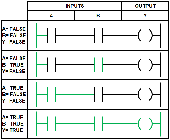
It is a graphical plc programming language which expresses logic operations with symbolic notation. Read about ladder diagrams (ladder logic) in our free electronics textbook. Introduction to plc ladder diagrams | free plc tutorials feb 10, 2016a very commonly used method of programming plcs is based on the use electrical wiring diagrams of the plc panel. Ladder logic (also known as ladder diagram or ld) is a programming language used to program a plc ( programmable logic controller ). The underlying program uses boolean with simulink® plc coder™, you can use ladder import to import ladder diagrams created with rockwell automation® ides, such as rslogix™ 5000. Motor control circuits ladder logic electronics textbook. Plc ladder circuit examples, plc logo wiring, plc relay circuit, plc wiring connection, siemens plc wiring tutorial. Assortment of plc panel wiring diagram pdf. A ladder diagram is one of the simplest methods used to program a plc. Ladder diagram basics ladder diagram examples wiring. We can redraw this diagram in a different way, using two vertical lines to represent the input power rails and stringing the. The diagram shows the circuit for switching on or off an electric motor. When the plc is in its run mode, it goes through the entire ladder program to the end, the end rung of the program is clearly denoted, and then promptly resumes at the.