Home
› Trailer Light Plug Diagram / Wiring A Boat Trailer For Brakes And Lights : Below is a diagram of a 13 pin euro trailer plug with coloured pins as they are wired.
Trailer Light Plug Diagram / Wiring A Boat Trailer For Brakes And Lights : Below is a diagram of a 13 pin euro trailer plug with coloured pins as they are wired.
Trailer Light Plug Diagram / Wiring A Boat Trailer For Brakes And Lights : Below is a diagram of a 13 pin euro trailer plug with coloured pins as they are wired.. Below is a diagram of a 13 pin euro trailer plug with coloured pins as they are wired. 6 way plug wiring diagr am standard wiring* post purpose wire color tm park lights brown gd ground black (or white) s trailer brakes blue lt left turn/brake light yellow rt right turn/brake light green a accessory red the most common variances on this diagram will be the (blue/brake) & (red/acc.) wires will be inverted. If you have a 13 pin socket fitted to your vehicle, adaptors to plug in so you can use a normal 7 pin plug are available. The first diagram is a simple set up of two brake lights, two indicators and two side lights. Trailer wiring diagrams 4 way systems.
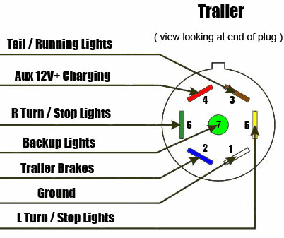
By law, trailer lighting must be connected into the tow vehicle's wiring system to provide trailer running lights, turn signals and brake lights. 7 way plug wiring diagram standard wiring* post purpose wire color tm park light green (+) battery feed black rt right turn/brake light brown lt left turn/brake light red s trailer electric brakes blue gd ground white a accessory yellow this is the most common (standard) wiring scheme for rv plugs and the one used by major auto manufacturers today. Right turn signal / stop light (green), left turn signal / stop light (yellow), taillight / license / side marker (brown) and a ground (white). The second diagram shows two brake lights, two indicators, two side lights and a fog light. Jun 09, 2011 · here are two wiring diagrams for the 7 pin 'n' type trailer electrical plug.
7 Way Diagram Aj S Truck Trailer Center from www.ajtnt.com Below is a diagram of a 13 pin euro trailer plug with coloured pins as they are wired. 4 way flat molded connectors allow basic hookup for three lighting functions; The table and diagram below explains the connections used on a 7 pin setup. The first diagram is a simple set up of two brake lights, two indicators and two side lights. Click on the image below to enlarge it. In some cases and more often in europe the trailer light will be connected using a 13 pin plug and socket. Click on the image below to enlarge it. The second diagram shows two brake lights, two indicators, two side lights and a fog light.
Wiring diagram trailer _ sabs 7core.cdr author:
Click on the image below to enlarge it. 4 way flat molded connectors allow basic hookup for three lighting functions; Jun 09, 2011 · here are two wiring diagrams for the 7 pin 'n' type trailer electrical plug. In some cases and more often in europe the trailer light will be connected using a 13 pin plug and socket. Trailer wiring diagrams 4 way systems. If you have a 13 pin socket fitted to your vehicle, adaptors to plug in so you can use a normal 7 pin plug are available. Click on the image below to enlarge it. Wiring diagram for a 13pin euro trailer plug. The first diagram is a simple set up of two brake lights, two indicators and two side lights. The 7 pin 'n' type (12n) plug will still be used on o1 trailers and many towbar fitters will still offer the 7 pin socket as the cheapest alternative. Wiring diagram trailer _ sabs 7core.cdr author: Right turn signal / stop light (green), left turn signal / stop light (yellow), taillight / license / side marker (brown) and a ground (white). A colour coded trailer plug wiring guide to help you require your plugs and sockets.
Below is a diagram of a 13 pin euro trailer plug with coloured pins as they are wired. Wiring diagram trailer _ sabs 7core.cdr author: If your vehicle is not equipped with a working trailer wiring harness, there are a number of different solutions to provide the perfect fit for. Wiring diagram for a 13pin euro trailer plug. Trailer wiring diagrams 4 way systems.
Solved I Need An F150 Trailer Towing Wiring Diagram Fixya from www.fixya.com The second diagram shows two brake lights, two indicators, two side lights and a fog light. Wiring diagram for a 13pin euro trailer plug. The 7 pin 'n' type (12n) plug will still be used on o1 trailers and many towbar fitters will still offer the 7 pin socket as the cheapest alternative. The table and diagram below explains the connections used on a 7 pin setup. A colour coded trailer plug wiring guide to help you require your plugs and sockets. Click on the image below to enlarge it. Trailer electrical connectors come in a variety of shapes and sizes. If your vehicle is not equipped with a working trailer wiring harness, there are a number of different solutions to provide the perfect fit for.
The table and diagram below explains the connections used on a 7 pin setup.
6 way plug wiring diagr am standard wiring* post purpose wire color tm park lights brown gd ground black (or white) s trailer brakes blue lt left turn/brake light yellow rt right turn/brake light green a accessory red the most common variances on this diagram will be the (blue/brake) & (red/acc.) wires will be inverted. Trailer electrical connectors come in a variety of shapes and sizes. The second diagram shows two brake lights, two indicators, two side lights and a fog light. Below is a diagram of a 13 pin euro trailer plug with coloured pins as they are wired. Includes guides for 7 pin, 6pin, 5 pin, 12 pin, 13 pin, pin and heavy duty round plugs and sockets. The table and diagram below explains the connections used on a 7 pin setup. By law, trailer lighting must be connected into the tow vehicle's wiring system to provide trailer running lights, turn signals and brake lights. A colour coded trailer plug wiring guide to help you require your plugs and sockets. 7 way plug wiring diagram standard wiring* post purpose wire color tm park light green (+) battery feed black rt right turn/brake light brown lt left turn/brake light red s trailer electric brakes blue gd ground white a accessory yellow this is the most common (standard) wiring scheme for rv plugs and the one used by major auto manufacturers today. Trailer wiring diagrams 4 way systems. The first diagram is a simple set up of two brake lights, two indicators and two side lights. If you have a 13 pin socket fitted to your vehicle, adaptors to plug in so you can use a normal 7 pin plug are available. Wiring diagram trailer _ sabs 7core.cdr author:
Trailer wiring diagrams 4 way systems. Click on the image below to enlarge it. Click on the image below to enlarge it. 6 way plug wiring diagr am standard wiring* post purpose wire color tm park lights brown gd ground black (or white) s trailer brakes blue lt left turn/brake light yellow rt right turn/brake light green a accessory red the most common variances on this diagram will be the (blue/brake) & (red/acc.) wires will be inverted. If your vehicle is not equipped with a working trailer wiring harness, there are a number of different solutions to provide the perfect fit for.
Trailer And Towed Light Hookups from www.myrv.us In some cases and more often in europe the trailer light will be connected using a 13 pin plug and socket. Right turn signal / stop light (green), left turn signal / stop light (yellow), taillight / license / side marker (brown) and a ground (white). A colour coded trailer plug wiring guide to help you require your plugs and sockets. Trailer electrical connectors come in a variety of shapes and sizes. The second diagram shows two brake lights, two indicators, two side lights and a fog light. 4 way flat molded connectors allow basic hookup for three lighting functions; The first diagram is a simple set up of two brake lights, two indicators and two side lights. If your vehicle is not equipped with a working trailer wiring harness, there are a number of different solutions to provide the perfect fit for.
Click on the image below to enlarge it.
In some cases and more often in europe the trailer light will be connected using a 13 pin plug and socket. A colour coded trailer plug wiring guide to help you require your plugs and sockets. Includes guides for 7 pin, 6pin, 5 pin, 12 pin, 13 pin, pin and heavy duty round plugs and sockets. Click on the image below to enlarge it. If your vehicle is not equipped with a working trailer wiring harness, there are a number of different solutions to provide the perfect fit for. 6 way plug wiring diagr am standard wiring* post purpose wire color tm park lights brown gd ground black (or white) s trailer brakes blue lt left turn/brake light yellow rt right turn/brake light green a accessory red the most common variances on this diagram will be the (blue/brake) & (red/acc.) wires will be inverted. Trailer wiring diagrams 4 way systems. Wiring diagram trailer _ sabs 7core.cdr author: Click on the image below to enlarge it. The table and diagram below explains the connections used on a 7 pin setup. 4 way flat molded connectors allow basic hookup for three lighting functions; The second diagram shows two brake lights, two indicators, two side lights and a fog light. Trailer electrical connectors come in a variety of shapes and sizes.