Home
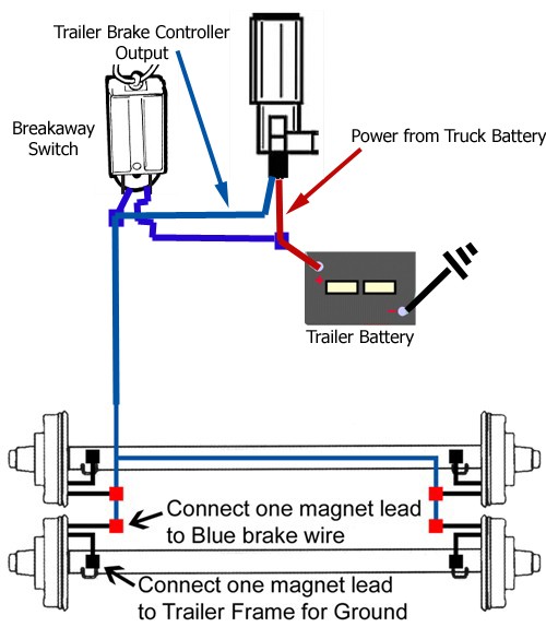
› Trailer Brake Wiring Diagram 7 Way - DIAGRAM Phillips 7 Way Trailer Plug Wiring Diagram Wiring Diagram FULL Version HD Quality ... / Many trailers are required to have a breakaway system on board.
Trailer Brake Wiring Diagram 7 Way - DIAGRAM Phillips 7 Way Trailer Plug Wiring Diagram Wiring Diagram FULL Version HD Quality ... / Many trailers are required to have a breakaway system on board.
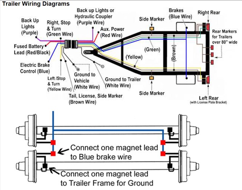
Trailer Brake Wiring Diagram 7 Way - DIAGRAM Phillips 7 Way Trailer Plug Wiring Diagram Wiring Diagram FULL Version HD Quality ... / Many trailers are required to have a breakaway system on board.. A 4 pin connector is almost always used on trailers that do not utilize electric trailer brakes nor have any need for accessory power and therefore the trailer only requires power for lights. 7 way plug wiring diagram standard wiring* post purpose wire color tm park light green (+) battery feed black rt right turn/brake light brown lt left turn/brake light red s trailer electric brakes blue gd ground white a accessory yellow this is the most common (standard). Uneven braking occurs when the length of the wire between each of the magnet connections adds resistance and therefore electric brake wiring: There are two ways to do trailer brake wiring, the right way and the wrong way. I use it for the electric brake controller on non air brake trailers.
Use this as a reference when working on your boat trailer wiring. This junction box provides a fast, easy way to connect wires from the trailer connector to the trailer wiring. Trailer plug wiring is standardized across all vehicles, no point trying to find vehicle specific info. The trailer wiring diagrams listed below, should help identify any wiring issues you may have with your trailer. The question is if i cut the wires at the hitch side will it work with the diagrams shown.
Building Tiny House on Flatbed Trailer and Need Brake Controller and Wiring for Electric Brakes ... from www.etrailer.com Along with a universal brake control installation kit: I'm looking to get oem 7 pin and 4 way flat to work. When wiring your trailer, be sure to route your wiring so that all wires are tucked in and away from anything that could rub or catch on them. Some may be made that way but the ones i've pulled are better. Trailer wiring color code explanation. Please follow bougerv trailer wiring diagram in description or manual. This junction box provides a fast, easy way to connect wires from the trailer connector to the trailer wiring. Includes 5 and 7 wire plug and trailer wiring schematics.
Pinout diagrams, minimum wire sizes, and common wire colors for 4 pin, 6 pin, and 7 pin truck/trailer connectors.
Wiring diagram very best 7 prong trailer wiring diagram fascinating top hat trailers wiring diagram wiring diagram blog. Uneven braking occurs when the length of the wire between each of the magnet connections adds resistance and therefore electric brake wiring: I have a 1996 tracker marine boat trailer that has a problem with the brakes.the brakes will not release. If not, the structure won't function as it ought to be…. Offroaders staff editor trailer & towing. 1 way trailer brakes can get you killed.if you are going down a long steep grade (hill) your car/truck brakes (which are only made to stop your car or truck) will get hot and glaze over and eventually. Basically, this is a way of applying the trailer brakes if the the trailer wiring diagram shows this wire going to all the lights and brakes. The brake lights come off the f15 10amp fuse in the main fuse block on my 05ml. Find the trailer light wiring diagram below that corresponds to your existing configuration. Use this as a reference when working on your boat trailer wiring. A 4 pin connector is almost always used on trailers that do not utilize electric trailer brakes nor have any need for accessory power and therefore the trailer only requires power for lights. Whoever put the trailer wiring on either cross wired something or a wire got pinched somewhere. Round 1 1/4 diameter metal connector allows 1 or 2 additional wiring and lighting functions such as back up lights, auxiliary 12v power or electric.
This junction box provides a fast, easy way to connect wires from the trailer connector to the trailer wiring. Same as 4 way system listed above but adds a extra blue wire for brake signal or auxiliary power. Trailer plug wiring is standardized across all vehicles, no point trying to find vehicle specific info. This requires a switch to go from one. Also, it must connect with things (if included) that use the aux.
Wiring a Trailer Breakaway Kit on a Bigfoot Travel Trailer | etrailer.com from www.etrailer.com The diagram below shows the proper way to wire the connector to your trailer or vehicle. I use it for the electric brake controller on non air brake trailers. A 4 pin connector is almost always used on trailers that do not utilize electric trailer brakes nor have any need for accessory power and therefore the trailer only requires power for lights. The thing is i have to go to the tail lights to make attachments. This color trailer wiring diagram will help you when you need to connect your trailer to your truck's if you've got bright, well functioning brake lights on the trailer, these lights will catch the attention of the drivers always be extra aware of everything going on around you, and give everyone the right of way. The question is if i cut the wires at the hitch side will it work with the diagrams shown. The following page contains information about trailer to vehicle wiring diagrams including: Whoever put the trailer wiring on either cross wired something or a wire got pinched somewhere.
Offroaders staff editor trailer & towing.
If not, the structure won't function as it ought to be…. Yellow = left turn green = right turn brown = tail/marker blue = trailer brakes black = +12 volt source (ie breakaway battery charge) orange = backup/auxillary white = ground. Along with a universal brake control installation kit: Uneven braking occurs when the length of the wire between each of the magnet connections adds resistance and therefore electric brake wiring: Includes 5 and 7 wire plug and trailer wiring schematics. Here are the standard wiring color sequence: 7 way plug wiring diagram standard wiring* post purpose wire color tm park light green (+) battery feed black rt right turn/brake light brown lt left turn/brake light red s trailer electric brakes blue gd ground white a accessory yellow this is the most common (standard). The brake lights come off the f15 10amp fuse in the main fuse block on my 05ml. It is an orange wire. Whoever put the trailer wiring on either cross wired something or a wire got pinched somewhere. A 4 pin connector is almost always used on trailers that do not utilize electric trailer brakes nor have any need for accessory power and therefore the trailer only requires power for lights. I have a 1996 tracker marine boat trailer that has a problem with the brakes.the brakes will not release. Trailer wiring color code explanation.
Doing your trailer wiring this way will cost a bit more than the ready made kits, and takes a bunch more time to install, but in the long run pin 7 is always hot on abs equipped trailers with air brakes; The 7 way from the trailer then plugs into the prodigy controller module you just mounted on the trailer. The diagram below shows the proper way to wire the connector to your trailer or vehicle. Trailer wiring color code explanation. I use it for the electric brake controller on non air brake trailers.
Dodge Ram 7 Pin Trailer Wiring Diagram | Trailer Wiring Diagram from trailer-wiring-diagram.com Uneven braking occurs when the length of the wire between each of the magnet connections adds resistance and therefore electric brake wiring: I'm looking to get oem 7 pin and 4 way flat to work. Boat trailer color wiring diagram. Trailer wiring color code explanation. 7 wire trailer circuit, 6 wire trailer circuit, 4 wire trailer circuit and other trailer wiring diagrams. Pinout diagrams, minimum wire sizes, and common wire colors for 4 pin, 6 pin, and 7 pin truck/trailer connectors. If not, the structure won't function as it ought to be…. Each component ought to be placed and linked to different parts in particular way.
Travel trailers don't have separate brake battery.
Travel trailers don't have separate brake battery. Boat trailer color wiring diagram. Wiring diagram very best 7 prong trailer wiring diagram fascinating top hat trailers wiring diagram wiring diagram blog. The brake lights come off the f15 10amp fuse in the main fuse block on my 05ml. Also, it must connect with things (if included) that use the aux. Use this as a reference when working on your boat trailer wiring. The following page contains information about trailer to vehicle wiring diagrams including: Yellow = left turn green = right turn brown = tail/marker blue = trailer brakes black = +12 volt source (ie breakaway battery charge) orange = backup/auxillary white = ground. Whoever put the trailer wiring on either cross wired something or a wire got pinched somewhere. I use it for the electric brake controller on non air brake trailers. Trailer wiring color code explanation. 7 way plug wiring diagram standard wiring* post purpose wire color tm park light green (+) battery feed black rt right turn/brake light brown lt left turn/brake light red s trailer electric brakes blue gd ground white a accessory yellow this is the most common (standard). Doing your trailer wiring this way will cost a bit more than the ready made kits, and takes a bunch more time to install, but in the long run pin 7 is always hot on abs equipped trailers with air brakes;