Home
› Class H Amplifier Circuit Diagram / Gated Class H Amplifier Line Driver System And Method Diagram Schematic And Image 06 : Is effective to both ac and dc input signals.
Class H Amplifier Circuit Diagram / Gated Class H Amplifier Line Driver System And Method Diagram Schematic And Image 06 : Is effective to both ac and dc input signals.
Class H Amplifier Circuit Diagram / Gated Class H Amplifier Line Driver System And Method Diagram Schematic And Image 06 : Is effective to both ac and dc input signals.. The circuit is simple, yet is capable of excellent performance. We are going to be discussing how amplifiers conduct through waveforms, so a basic diagram of a anywho, i have class a/b and g (h?) amps, as well as a couple se tube jobs, which don't amplify particularly well but they sure deliver the chocolaty mids. Irs2092 stereo class d amplifier schematic. I am not a hifi geek, i just wanted to build a simple stereo amplifier that could drive some speakers for my desktop computer. This is one of a great many configurations that have been used, and in that respect can be considered as 'typical'.
The classes are related to the time period that the active amplifier device is passing current. In this audio/power amplifier circuit design tutorial, we will build a 100w rms output power amplifier using mosfets and transistors with a 4 ohms impedance speaker connected to it. Is video mein ham class h amplifier ka ek practical circuit diagram ki study karenge ki aur aane wale agale video mein iska pcb design karke practically. The collection of electronic circuit diagram ( circuitdiagram.net ) fans page. It's an 8 transistor circuit diagram.
2000w Audio Amplifier Circuit Diagrams 110 Atv Wiring Schematics For Wiring Diagram Schematics from solderingmind.com 24v to 220v 1000w dc ac sine wave inverter for photovoltaic solar system. Both inner and outer transistors use separate drivers. This stereo amplifier circuit diagram is cheap and simple. Inductor l1 and capacitor c1 forms a tank circuit which aids in the extraction of the required signal from the pulsed output of the transistor. The collection of electronic circuit diagram ( circuitdiagram.net ) fans page. As you can see in the above block diagram, power amplifier is the last stage which is directly connected to the load. In this audio/power amplifier circuit design tutorial, we will build a 100w rms output power amplifier using mosfets and transistors with a 4 ohms impedance speaker connected to it. Depending upon their mode of operation, there are class a, class b and class c amplifiers.
Power amplifiers − the amplifier circuit that amplifies the signals that lie in a very high frequency range, is called as power amplifier.
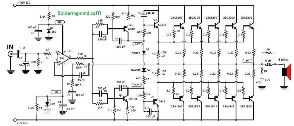
In this audio/power amplifier circuit design tutorial, we will build a 100w rms output power amplifier using mosfets and transistors with a 4 ohms impedance speaker connected to it. I designed it specifically for use as an amplifier for the digital sound card in my computer. 825 x 610 jpeg 55 кб. In electronics, power amplifier classes are letter symbols applied to different power amplifier types. Here in this article, we can get transistor audio amplifier circuit diagram to make our amplifier. Power amplifiers − the amplifier circuit that amplifies the signals that lie in a very high frequency range, is called as power amplifier. 12v fan on 230v circuit. Irs2092 stereo class d amplifier schematic. 12v to 24v dc converter power supply circuit diagram. Class c power amplifier is a type of amplifier where the active element (transistor) conduct for less than one half cycle of the input signal. 24v to 220v 1000w dc ac sine wave inverter for photovoltaic solar system. I am not a hifi geek, i just wanted to build a simple stereo amplifier that could drive some speakers for my desktop computer. An amplifier is an electronic device or circuit which is used to increase the magnitude of the signal applied to its input.
Chris is right about the low. Power amplifiers − the amplifier circuit that amplifies the signals that lie in a very high frequency range, is called as power amplifier. Figure 1 shows the block diagram of one of the two identical channels of the tda7498. Carvin x amp quad equalizer circuit diagram. Both inner and outer transistors use separate drivers.
Project 5 Buildaudioamps from buildaudioamps.com 863 x 505 jpeg 70 кб. 12v fan on 230v circuit. Home amplifier circuit diagrams irs2092 stereo class d amplifier schematic circuit diagram. As you can see in the above block diagram, power amplifier is the last stage which is directly connected to the load. This is one of a great many configurations that have been used, and in that respect can be considered as 'typical'. Both inner and outer transistors use separate drivers. The circuit is simple, yet is capable of excellent performance. The collection of electronic circuit diagram ( circuitdiagram.net ) fans page.
12v fan on 230v circuit.
Class h is an analog amplifier which aims to improve the efficiency of the amplifier b / ab class. The class gives a broad indication of an amplifier's characteristics and performance. Transistor audio amplifier circuit diagram. Improved 3 transistor audio amp electronic circuit. Please remember that always use original or good quality one transistor. This stereo amplifier circuit diagram is cheap and simple. 825 x 610 jpeg 55 кб. Ensure that the output transistor never has a simultaneously high voltage across its terminals and a high. Home amplifier circuit diagrams irs2092 stereo class d amplifier schematic circuit diagram. This is one of a great many configurations that have been used, and in that respect can be considered as 'typical'. Both inner and outer transistors use separate drivers. With the genlede irs2092, much higher power class d amplifier circuits are being built, but the cost is rising as the power rises, with rms 2x50w with output power 4 ohm speakers in. 1 is the basic diagram of an amplifier circuit unit, which.
In this audio/power amplifier circuit design tutorial, we will build a 100w rms output power amplifier using mosfets and transistors with a 4 ohms impedance speaker connected to it. Ensure that the output transistor never has a simultaneously high voltage across its terminals and a high. 2000w high power amplifier circuit diagram final transistor using transistor 2sc5359 and 2sa1987, power amplifier circuit is very strong power super high power amplifier called yiroshi audio is most powerful it has output power about 1000w up to 3000w, you can see the circuit diagram, pcb. Documents similar to class h amplifier. Is effective to both ac and dc input signals.
Amplifier Classes From A To H Circuit Cellar from i2.wp.com The other aspect of i have used and repaired many of the carver amps with the triac circuit. A class d amplifier also termed as a digital amplifier uses pulse width modulation or pwm technology for amplifying the fed small amplitude analogue the proposed design of a class d digital amplifier circuit utilizes the famous 555 ic for the intended comparisons. Tda2030 is a monolithic integrated circuit in pentawatt package, intended for use as a low frequency class ab . tda2005 is a class b dual audio power amplifier specifically designed for car radio applications. Chris is right about the low. Instead of the pwm method here we. This stereo amplifier circuit diagram is cheap and simple. Ensure that the output transistor never has a simultaneously high voltage across its terminals and a high. Transistor audio amplifier circuit diagram.
The circuit is simple, yet is capable of excellent performance.
Figure 1 shows the block diagram of one of the two identical channels of the tda7498. Is effective to both ac and dc input signals. Is video mein ham class h amplifier ka ek practical circuit diagram ki study karenge ki aur aane wale agale video mein iska pcb design karke practically. The classes are related to the time period that the active amplifier device is passing current. With the genlede irs2092, much higher power class d amplifier circuits are being built, but the cost is rising as the power rises, with rms 2x50w with output power 4 ohm speakers in. Class h is an analog amplifier which aims to improve the efficiency of the amplifier b / ab class. Instead of the pwm method here we. This stereo amplifier circuit diagram is cheap and simple. I designed it specifically for use as an amplifier for the digital sound card in my computer. 12v fan on 230v circuit. Inductor l1 and capacitor c1 forms a tank circuit which aids in the extraction of the required signal from the pulsed output of the transistor. The collection of electronic circuit diagram ( circuitdiagram.net ) fans page. This is one of a great many configurations that have been used, and in that respect can be considered as 'typical'.