Home
› Wiring Diagram Switch Outlet : Wiring Two Lights - For wiring in series, the terminal screws are the means for passing voltage from one electrical outlet with to way switch in switch box wire diagram the pic below shows the electrical outlet gfci wiring diagram and step how to wiring multiple outlet gfci.
Wiring Diagram Switch Outlet : Wiring Two Lights - For wiring in series, the terminal screws are the means for passing voltage from one electrical outlet with to way switch in switch box wire diagram the pic below shows the electrical outlet gfci wiring diagram and step how to wiring multiple outlet gfci.
Wiring Diagram Switch Outlet : Wiring Two Lights - For wiring in series, the terminal screws are the means for passing voltage from one electrical outlet with to way switch in switch box wire diagram the pic below shows the electrical outlet gfci wiring diagram and step how to wiring multiple outlet gfci.. However, this diagram is a simplified variant of this arrangement. Jan 24, 18 02:09 pm. Ground is also connected to the ground terminal of a device (switch, receptacle, light fixture. These wiring diagrams will help you wire up your nitrous system or nitrous accessory. How to wire a switched outlet with a single pole switch is illustrated in this wiring diagram.
F electrical wiring diagram (system circuits). Wiring diagrams for switched wall outlets do it yourself. However, this diagram is a simplified variant of this arrangement. This wiring illustrates a switched outlet circuit with the source and switch coming first. There are only three connections to be made, after all.
Wiring A Light Switch, Outlet Together Diagram Brilliant Wiring Diagrams, Switch To Control A ... from tonetastic.info Switch box wiring or switchboard wiring is a common wiring arrangement used in most house how to wire up a switchboard. Make sure that you have a jacketed wire running from the breaker to the outlet, and one from the switch to the outlet. Why is only half of the. In each electrical box, all ground wires are connected together. Wiring diagrams for switched wall outlets do it yourself. Have switch on combo device control outlet on device ground connection shown. Ground is also connected to the ground terminal of a device (switch, receptacle, light fixture. Diagrams also include a dryer outlet and typical ground connections.
In each electrical box, all ground wires are connected together.
Click on image for larger. Looking for a 3 way switch wiring diagram? These wiring diagrams will help you wire up your nitrous system or nitrous accessory. For example, a home builder will want to confirm the physical location of electrical outlets and light fixtures using a wiring diagram to avoid costly mistakes and building. If you have more than one outlet, you need to take @comintern's diagram, delete the white wire with black tape, extend the red wire all the way to the switch, and extend the white wire on the. There are only three connections to be made, after all. Take a closer look at a 3 way switch wiring diagram. Looking for a 3 way switch wiring diagram? How an outlet circuit works. Switch box wiring or switchboard wiring is a common wiring arrangement used in most house how to wire up a switchboard. Diagrams showing how outlets are wired using nm cable (romex). A wiring diagram is a visual representation of components and wires related to an electrical connection. Wiring electrical outlets (properly called receptacles) and switches involve many of the same basic techniques.
Make sure, however, to always turn power off at the main circuit panel before doing any electrical wiring. How an outlet circuit works. For example, a home builder will want to confirm the physical location of electrical outlets and light fixtures using a wiring diagram to avoid costly mistakes and building. For wiring in series, the terminal screws are the means for passing voltage from one electrical outlet with to way switch in switch box wire diagram the pic below shows the electrical outlet gfci wiring diagram and step how to wiring multiple outlet gfci. However, this diagram is a simplified variant of this arrangement.
How To Wire A Switched Outlet Power To Receptacle from www.chanish.org Diagrams showing how outlets are wired using nm cable (romex). F electrical wiring diagram (system circuits). Have switch on combo device control outlet on device ground connection shown. A wiring diagram is a simple visual representation of the physical connections and physical layout of an electrical system or circuit. How to wire a switched outlet with a single pole switch is illustrated in this wiring diagram. Here is the wiring symbol legend, which is a detailed documentation of common symbols that are used in wiring diagrams, home wiring plans, and electrical wiring blueprints. Wiring diagrams for switched wall outlets do it yourself. Here are a few that may be of interest.
Have switch on combo device control outlet on device ground connection shown.
These wiring diagrams will help you wire up your nitrous system or nitrous accessory. Ground is also connected to the ground terminal of a device (switch, receptacle, light fixture. It makes the process of building circuit simpler. Diagrams showing how outlets are wired using nm cable (romex). In each electrical box, all ground wires are connected together. However, this diagram is a simplified variant of this arrangement. For example, a home builder will want to confirm the physical location of electrical outlets and light fixtures using a wiring diagram to avoid costly mistakes and building. The diagram offers visual representation of an electric arrangement. A wiring diagram is a simple visual representation of the physical connections and physical layout of an electrical system or circuit. This allows for a separate. This wiring illustrates a switched outlet circuit with the source and switch coming first. The diagrams listed are for your use as a simple reference to use when you are doing your wiring. Jan 24, 18 02:09 pm.
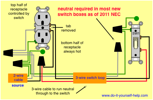
Tools and supplies you will need. This pictorial diagram shows us the physical links that are far easy to understand an the wire is tied with a wire going to the black wire and switch, which is further going to the outlet. Wiring diagram of a switched electrical receptacle outlet and an unswitched electrical receptacle outlet with the power entering the switched outlet electrical box from the circuit breaker panel. Making them at the proper place is a little more. There are two switched outlet wiring diagrams below that depict split outlet wiring.
What is the wiring schematic of a GFCI? - Quora from qph.fs.quoracdn.net If you need help, reference the diagram below. If you have more than one outlet, you need to take @comintern's diagram, delete the white wire with black tape, extend the red wire all the way to the switch, and extend the white wire on the. Have switch on combo device control outlet on device ground connection shown. Play it smart and stay safe when wiring outlets and switches. Make sure, however, to always turn power off at the main circuit panel before doing any electrical wiring. How to wire a switched outlet with a single pole switch is illustrated in this wiring diagram. There are two switched outlet wiring diagrams below that depict split outlet wiring. The diagrams listed are for your use as a simple reference to use when you are doing your wiring.
Here is the wiring symbol legend, which is a detailed documentation of common symbols that are used in wiring diagrams, home wiring plans, and electrical wiring blueprints.
This page contains several diagrams for wiring a switch to control one or more receptacle outlets including a split receptacle and multiple outlets wired together. If you have more than one outlet, you need to take @comintern's diagram, delete the white wire with black tape, extend the red wire all the way to the switch, and extend the white wire on the. For example, a home builder will want to confirm the physical location of electrical outlets and light fixtures using a wiring diagram to avoid costly mistakes and building. There are only three connections to be made, after all. Wiring diagrams use simplified symbols to represent switches, lights, outlets, etc. Here is the wiring symbol legend, which is a detailed documentation of common symbols that are used in wiring diagrams, home wiring plans, and electrical wiring blueprints. Click on image for larger. Diagrams also include a dryer outlet and typical ground connections. This pictorial diagram shows us the physical links that are far easy to understand an the wire is tied with a wire going to the black wire and switch, which is further going to the outlet. Here are a few that may be of interest. F electrical wiring diagram (system circuits). Three or four button switch panel wiring diagram. This wiring illustrates a switched outlet circuit with the source and switch coming first.