Home
› Electrical Circuit Diagram Symbols : How To Read And Understand An Electrical Schematic - Later when you come across symbols you don't know, you can come back here to identify what it is.
Electrical Circuit Diagram Symbols : How To Read And Understand An Electrical Schematic - Later when you come across symbols you don't know, you can come back here to identify what it is.
Electrical Circuit Diagram Symbols : How To Read And Understand An Electrical Schematic - Later when you come across symbols you don't know, you can come back here to identify what it is.. It is highly recommended that the design engineer show test switches on the. Thus in circuit diagrams and schematics, graphical symbols identify and represent electrical and electronic devices and show how they are electrically connected together while drawing lines between them represents the wires or component leads. Ciircuits, diagrams & symbols includes: > edraw symbol > electrical symbols for electrical schematic diagrams. Electrical current transfers energy around circuits.
Click on each link given below to view the symbols. Example hints connect circuits diagram circuit diagram example figure e placement of power rails and conventions for device alignment exampl. They are also known as circuit symbols or schematic symbols as they are used in electrical schematics and diagrams. Electrical symbols and electronic circuit symbols are used for drawing schematic diagram. An electronic symbol is a pictogram used to represent various electrical and electronic devices such as wires, batteries, resistors, and tr.
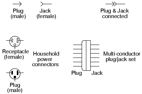
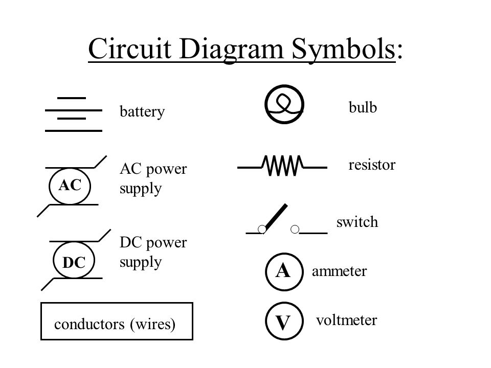
Lessons In Electric Circuits Volume V Reference Chapter 9 from www.ibiblio.org A pictorial circuit diagram uses simple images of components, while a schematic diagram shows the components and interconnections of the circuit using. A ground symbol (iec symbol 5017) identifies a ground terminal. Thus in circuit diagrams and schematics, graphical symbols identify and represent electrical and electronic devices and show how they are electrically connected together while drawing lines between them represents the wires or component leads. Our circuit diagram symbol library is schematic and includes many icons commonly used by engineers. Click on each link given below to view the symbols. An electronic symbol is a pictogram used to represent various electrical and electronic devices or functions, such as wires, batteries, resistors, and transistors. Complete circuit symbols of electronic components. Circuit or schematic diagrams consist of symbols representing physical components and lines representing wires or electrical conductors.
Example hints connect circuits diagram circuit diagram example figure e placement of power rails and conventions for device alignment exampl.
All circuit symbols are in standard format and can be used for drawing schematic circuit diagram and layout. Electronics explained in a simple way. Click on each link given below to view the symbols. Learn about and revise electrical circuits, charge, current, power and resistance with gcse bitesize combined science. Electrical circuit is an interconnection of electrical components. This version recognizes that electrical diagrams are a factor in international trade: Electrical diagram symbols represents devices and components of electrical and electronic circuits. Create electrical circuit diagrams and schematics with electrical symbols provided by smartdraw software. Circuit or schematic diagrams consist of symbols representing physical components and lines representing wires or electrical conductors. To read and interpret electrical diagrams and schematics, the basic symbols and conventions used in the drawing must be understood. Learn to read electrical and electronic circuit diagrams or schematics. It is highly recommended that the design engineer show test switches on the. They are also known as circuit symbols or schematic symbols as they are used in electrical schematics and diagrams.
A circuit is a closed path where electrons flow in a wire. Circuit symbols are used in circuit diagrams which show how a circuit is connected together. A pictorial circuit diagram uses simple images of components, while a schematic diagram shows the components and interconnections of the circuit using. Circuit or schematic diagrams consist of symbols representing physical components and lines representing wires or electrical conductors. Electrical symbols and electronic circuit symbols are used for drawing schematic diagram.
Electrical Circuits Making Electricity Useful Circuit Diagrams Electrical Circuits Can Be Shown In Diagrams Using Symbols 9 0v Ppt Download from images.slideplayer.com Circuit diagrams show how electronic components are connected together. A circuit is a closed path where electrons flow in a wire. Later when you come across symbols you don't know, you can come back here to identify what it is. Electricians depend upon an electric circuit diagram for initiating any building wiring. Our circuit diagram symbol library is schematic and includes many icons commonly used by engineers. This version recognizes that electrical diagrams are a factor in international trade: As an illustration of the use of electrical symbols in schematic diagrams, consider the following two 1. Electrical symbols are the standard technique to represent an electrical circuit.
Electrical symbols are the standard technique to represent an electrical circuit.
Complete circuit symbols of electronic components. They are also known as circuit symbols or schematic symbols as they are used in electrical schematics and diagrams. These electrical circuits are demonstrated by lines to represent wires and symbols to represent electrical & electronic constituents, as it aids in better apprehending the connection between distinct components. Create electrical circuit diagrams and schematics with electrical symbols provided by smartdraw software. An electrical network consists of a closed loop. As nowadays there is no single standard. Circuit symbols overview resistors capacitors inductors, coils, chokes & transformers diodes distinct symbols have been used to depict the different types of electronic components in circuits, since the very beginning of electrical and electronic science. Electrical circuit is an interconnection of electrical components. It makes the graphical representation easier to work on and implement. Circuit symbols are used in circuit diagrams which show how a circuit is connected together. Our circuit diagram symbol library is schematic and includes many icons commonly used by engineers. There are many electronic symbols in electronic circuits that are used to represent or identify a basic electronic or electrical device. The symbols represent electrical and electronic components.
Electrical current transfers energy around circuits. It is highly recommended that the design engineer show test switches on the. These electrical circuits are demonstrated by lines to represent wires and symbols to represent electrical & electronic constituents, as it aids in better apprehending the connection between distinct components. Circuit symbols overview resistors capacitors inductors, coils, chokes & transformers diodes distinct symbols have been used to depict the different types of electronic components in circuits, since the very beginning of electrical and electronic science. Electrical circuits library contains 49 electrical element symbols of electrical and electronic devices, including ignitors, starters, transmitters, circuit protectors, transducers, radio and audio equipment.
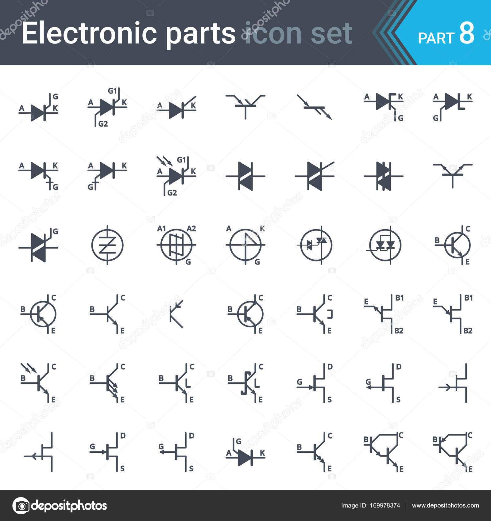
Electric And Electronic Circuit Diagram Symbols Set Of Thyristors Triacs Diacs And Transistors Vector Image By C Sylas83 Vector Stock 169978374 from st3.depositphotos.com Circuit symbols overview resistors capacitors inductors, coils, chokes & transformers diodes distinct symbols have been used to depict the different types of electronic components in circuits, since the very beginning of electrical and electronic science. An electronic symbol is a pictogram used to represent various electrical and electronic devices such as wires, batteries, resistors, and tr. Circuit or schematic diagrams consist of symbols representing physical components and lines representing wires or electrical conductors. Circuit symbols and circuit diagrams. There are many electronic symbols in electronic circuits that are used to represent or identify a basic electronic or electrical device. Electrical current transfers energy around circuits. Electrical circuit is an interconnection of electrical components. There are two types of current:
A pictorial circuit diagram uses simple images of components, while a schematic diagram shows the components and interconnections of the circuit using.
As an illustration of the use of electrical symbols in schematic diagrams, consider the following two 1. Create electrical circuit diagrams and schematics with electrical symbols provided by smartdraw software. Circuit diagrams show how electronic components are connected together. Electrical diagram symbols represents devices and components of electrical and electronic circuits. An electrical network consists of a closed loop. The symbols represent electrical and electronic components. Electrical circuit is an interconnection of electrical components. There are many electronic symbols in electronic circuits that are used to represent or identify a basic electronic or electrical device. They are also known as circuit symbols or schematic symbols as they are used in electrical schematics and diagrams. This physics video tutorial explains how to read a schematic diagram by knowing what each electric symbol represent in a typical electrical circuit. Circuit symbols overview resistors capacitors inductors, coils, chokes & transformers diodes distinct symbols have been used to depict the different types of electronic components in circuits, since the very beginning of electrical and electronic science. Electricians depend upon an electric circuit diagram for initiating any building wiring. Circuit symbols are used in circuit diagrams which show how a circuit is connected together.