Home
› Lcd Display Wiring Diagram / Hd44780 Character Lcd Displays Part 1 Protostack - Besides complex display units like graphic displays and 3d dispays, one must know working with simple displays like 16x1 and 16x2 units.
Lcd Display Wiring Diagram / Hd44780 Character Lcd Displays Part 1 Protostack - Besides complex display units like graphic displays and 3d dispays, one must know working with simple displays like 16x1 and 16x2 units.
Lcd Display Wiring Diagram / Hd44780 Character Lcd Displays Part 1 Protostack - Besides complex display units like graphic displays and 3d dispays, one must know working with simple displays like 16x1 and 16x2 units.. In this arduino lcd tutorial we will learn how to connect an lcd (liquid crystal display) to the arduino board. Connect the arduino board into your computer. Electrical wiring layouts are composed of 2 things: Check the com ports in windows device list. Eec arduino lcd wiring diagram wiring resources.
A detailed article on working of lcd (liquid crystal display) with picture and diagrams.lcd principle of operation and construction are also explained. The arduino will be responsible for reading. Tft lcd wiring diagram wire.bakemabuurt.nl. Lcds like these are very popular and broadly used in electronics projects as they are good for displaying information like sensors data from your project, and also they are very cheap. We are more focusing on 16×2 lcd.
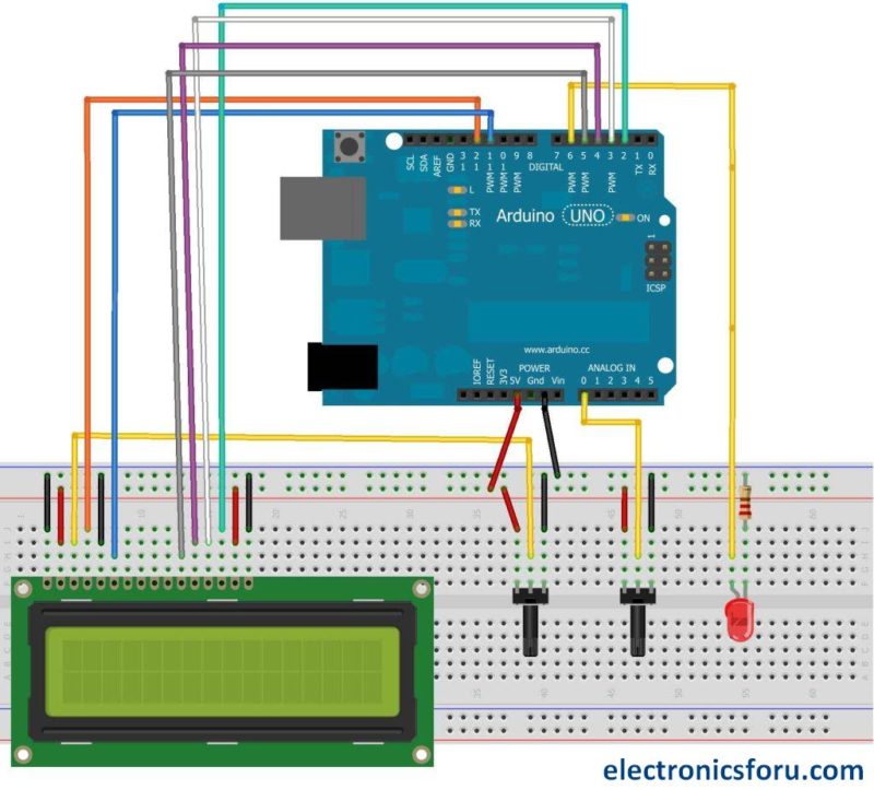
Character I2c Lcd With Arduino Tutorial 8 Examples from www.makerguides.com Display assembly diagram | laptop repair 101 a video signal from the motherboard goes to the lcd screen through the video cable. Wiring diagram for lm jc53 22ntm laptop lcd. Arduino lcd display wiring diagram source: This is the simple lcd display power supply circuit diagram. The lcd is always lit but no image. Funai lcd tv/dvd manual online: The blue color component you have seen in the above picture is a potentiometer. Wiring the lcd in 4 bit mode is usually preferred since it uses four less wires than 8 bit follow the diagram below to wire the lcd to your arduino:
It shows the parts of the circuit as streamlined forms, as well as the power and.
This is the simple lcd display power supply circuit diagram. Arduino lcd display wiring diagram source: If you happen to be better reading that looking at diagrams, let's go over the pinouts in detail. Arduino lcd display wiring diagram source: A typical value is 220. In this arduino lcd tutorial we will learn how to connect an lcd (liquid crystal display) to the arduino board. The connections are easy, see the image above with the breadboard circuit schematic. It shows the components of the circuit as simplified shapes, and the capacity and signal contacts in the company of the devices. Funai lcd tv/dvd manual online: The system we suggest consists of an lcd display, that is wired to the analog port of your arduino. Check the com ports in windows device list. All types of lcds, including i2c and display shields are covered here.article with code at. These lcds can be used to display information from the arduino or any sensor connected to it.
The process of controlling the display involves putting the data that form the image of what you want to display into the data registers, then putting instructions in the instruction register. A wiring diagram is a sort of schematic which makes use of abstract photographic signs to reveal all the affiliations of parts in a system. The liquid crystal library allows you to control lcd displays this example sketch shows how to use the display() and nodisplay() methods to turn on and off the circuit. It shows the parts of the circuit as streamlined forms, as well as the power and. Displaying sensor values on lcd arduino project hub.
16x2 Lcd Pinout Diagram Interfacing 16x2 Lcd With Arduino from www.electronicsforu.com Check the com ports in windows device list. Wiring diagram for lm jc53 22ntm laptop lcd. All circuits are the same ~ voltage, ground, individual component, and changes. Tft lcd wiring diagram wire.bakemabuurt.nl. For example, you can create a temperature monitoring lcds are one of the easiest devices you can use to display the output from arduino projects. The lcd has one display input buffer per overlay that fetches pixels through the dual ahb master interface and a lookup table to allow palletized display the block diagram and the tables below explain the meaning of the i/o needed to interface a standard lcd panel. We are more focusing on 16×2 lcd. The arduino will be responsible for reading.
Copy of fidget spinner rpm counter arduino project hub.
Effectively read a electrical wiring diagram, one provides to know how the particular components inside the system operate. Arduino lcd display wiring diagram source: Wiring the lcd in 4 bit mode is usually preferred since it uses four less wires than 8 bit follow the diagram below to wire the lcd to your arduino: Electrical wiring layouts are composed of 2 things: Display assembly diagram | laptop repair 101 a video signal from the motherboard goes to the lcd screen through the video cable. I print the schematic in addition to highlight the routine i'm diagnosing in order to make sure im staying on the path. The arduino will be responsible for reading. We always use devices made up of liquid crystal displays (lcds) like computers, digital watches and also dvd and cd players. Icons that represent the components in the circuit, and lines that stand for the connections between them. Learn to use lcd displays with an arduino. These displays can be wired in either 4 bit mode or 8 bit mode. Displaying sensor values on lcd arduino project hub. The process of controlling the display involves putting the data that form the image of what you want to display into the data registers, then putting instructions in the instruction register.
A generic display assembly includes a very few parts and knowing them will help you to understand witch part can cause a problem if you laptop video this week, display is completely gone. The process of controlling the display involves putting the data that form the image of what you want to display into the data registers, then putting instructions in the instruction register. Arduino lcd display wiring the geek pub. Eec arduino lcd wiring diagram wiring resources. Electrical wiring layouts are composed of 2 things:
Wiring A Character Lcd Character Lcds Adafruit Learning System from cdn-learn.adafruit.com A wiring diagram is a sort of schematic which makes use of abstract photographic signs to reveal all the affiliations of parts in a system. A typical value is 220. Before wiring the lcd screen to your arduino board we suggest to solder a pin header strip. Wiring the lcd in 4 bit mode is usually preferred since it uses four less wires than 8 bit follow the diagram below to wire the lcd to your arduino: There are many of them out there, and follow the diagram below to wire the lcd to your arduino: We always use devices made up of liquid crystal displays (lcds) like computers, digital watches and also dvd and cd players. All types of lcds, including i2c and display shields are covered here.article with code at. I print the schematic in addition to highlight the routine i'm diagnosing in order to make sure im staying on the path.
Lcds like these are very popular and broadly used in electronics projects as they are good for displaying information like sensors data from your project, and also they are very cheap.
Copy of fidget spinner rpm counter arduino project hub. For example, you can create a temperature monitoring lcds are one of the easiest devices you can use to display the output from arduino projects. It shows the components of the circuit as simplified shapes, and the capacity and signal contacts in the company of the devices. I print the schematic in addition to highlight the routine i'm diagnosing in order to make sure im staying on the path. Getting the arduino lcd display wiring project together relies on just a few simple parts. If you happen to be better reading that looking at diagrams, let's go over the pinouts in detail. Effectively read a electrical wiring diagram, one provides to know how the particular components inside the system operate. Electrical wiring layouts are composed of 2 things: A wiring diagram is a sort of schematic which makes use of abstract photographic signs to reveal all the affiliations of parts in a system. A typical value is 220. Print the wiring diagram off and use highlighters to be able to trace the signal. If you properly have seen the picture above, you will see a black adapter. The resistor in the diagram above sets the backlight brightness.