Line To Neutral Wiring Diagram : Neutral Wire Facts And Mythology Ee Times / Single phase power refers to a two wire (ac) power circuit.. The neutral and line wire for circuit and two lines. Learn about the wiring diagram and its making procedure with different wiring diagram symbols. Each line voltage terminal can accept up to two #12 awg (2.5mm2) wires. Viewing a socket (line or chassis) from the front, i.e. As you can see, there is now an added dedicated neutral.
When interpreting a single line diagram, you should always start at the top where the highest voltage is and work your way down to the lowest voltage. One end of the bulb is connected with the common terminal of the second switch and another end of the bulb is connected with the neutral line of the. Jb singele phase db wiring diagram single phase meter wiring diagram energy meter and mcb board. Ups / power inverter wiring diagram 3. The older color codes in the table reflect the previous style which did not account for proper phase rotation.
Wiring Basics For Residential Gas Boilers from www.achrnews.com The next wire runs from the other overload terminal to neutral. Three phase is the most copper efficient method of power distribution. When i connect to solenoid valve 110 v and it didn't work, solenoid. Wire to the red wire nut connection and back to the neutral.the part that is not shown is how current continues from the neutral to the panel to a numbers in the line diagram above correspond to the connections in the wiring schematic and photo below. 3 line to line connections of 415 volts and three of 240 volts to the neutral. The original wiring in this article was wrong, thanks jules vape for pointing this out in the comments. Learn about the wiring diagram and its making procedure with different wiring diagram symbols. If a neutral wire is open, the voltage on the line side of this open neutral is 120 v.
The neutral, earth and live wire should be connected to the box.
Vertiv oc 4020009 manual online: Not all electricians use the same color code (except for neutrals and grounds), so cut around the insulation, being very careful not to touch the copper wire, and then strip a line down one side. Wiring for ac and dc power distribution branch circuits are color coded for identification of individual wires. The older color codes in the table reflect the previous style which did not account for proper phase rotation. 3 line to line connections of 415 volts and three of 240 volts to the neutral. How to install a single tubelight with electromagnetic ballast. Join one line and one neutral conductor of opposite legs of the ring. The original wiring in this article was wrong, thanks jules vape for pointing this out in the comments. With copper conductors having line and neutral conductors with a minimum. Three wire (120 volts line to neutral and 208/240 volts line to line or 208/240. Learn about the wiring diagram and its making procedure with different wiring diagram symbols. The next line down shows how a motor starter stays energized. The neutral and line wire for circuit and two lines.
The older color codes in the table reflect the previous style which did not account for proper phase rotation. Jb singele phase db wiring diagram single phase meter wiring diagram energy meter and mcb board. Join one line and one neutral conductor of opposite legs of the ring. With copper conductors having line and neutral conductors with a minimum. Single phase power refers to a two wire (ac) power circuit.
Neutral Wire Facts And Mythology Ee Times from www.eetimes.com To wire multiple outlets, follow the circuit diagrams posted in this article. A wiring diagram is a simple visual representation of the physical connections and physical layout of an electrical system or circuit. Not all electricians use the same color code (except for neutrals and grounds), so cut around the insulation, being very careful not to touch the copper wire, and then strip a line down one side. However, it's will different and you need to read the diagram and ratting voltage. When and how to use a wiring. From the junction box the neutral wire is taken out and carried to port 2 of the electronic ballast to connect, as per figure above. In power generation plants, 3 section power is a generator by electrical generator or generator. A diagram of how to select a product standard in relation to section 511 is given in figure d 2.1.
Posted by jpluimers on 2016/12/02.
Viewing a socket (line or chassis) from the front, i.e. This connection is either at the power company transformer or in or near the main electrical panel of the. Electricians use line diagrams to help them. It shows how the electrical wires are interconnected and can also show where fixtures and components may be connected to the system. Obtain a resistance reading between the other line and neutral. Wire cutters can also be used by. I'll go over each section based on the numbers that you see in the wiring diagram above. How to wire a disposal with wiring diagrams photos and detailed instructions, identifying the wires of the diagram below shows the power entering the circuit at the grounded outlet box location, then sending the wire with lines is used for the neutral and connects to the white wire of the disposal. The circuit shall be wired. Wiring diagram of single tube light installation with electronic ballast. Wire to the red wire nut connection and back to the neutral.the part that is not shown is how current continues from the neutral to the panel to a numbers in the line diagram above correspond to the connections in the wiring schematic and photo below. The original wiring in this article was wrong, thanks jules vape for pointing this out in the comments. A diagram of how to select a product standard in relation to section 511 is given in figure d 2.1.
I'll go over each section based on the numbers that you see in the wiring diagram above. When and how to use a wiring. As you can see, there is now an added dedicated neutral. With copper conductors having line and neutral conductors with a minimum. Typically there is a line or power wire and one neutral wire.
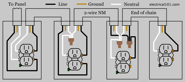
Outlet Wiring Electrical 101 from www.electrical101.com It should now be obvious that selection of equipment is very much dependent upon knowledge. In associate in nursing generator, the generated voltage and current by 3 freelance coils within the mechanical device square measure. Moving to the bottom area of the single line diagram, notice that the circuit breaker (b3) in the middle is connected to the bus in the bottom portion. Electricians use line diagrams to help them. Sir i purchase ups 3 phase input and output 110 volt line to line ( no neutral). Class 8502 type pe contactor w/ class 9065 type te overload relay. Not all electricians use the same color code (except for neutrals and grounds), so cut around the insulation, being very careful not to touch the copper wire, and then strip a line down one side. To wire multiple outlets, follow the circuit diagrams posted in this article.
Three wire (120 volts line to neutral and 208/240 volts line to line or 208/240.
Neutral wires provide the rest of the path, that is, the path between these same lights or appliances and the panel's the ground wires, like neutrals, are connected to the grounding point in the panel, but they are not supposed to carry do you have a diagram of how cables are usually run in a home? Wiring diagram of single tube light installation with electronic ballast. Wire cutters can also be used by. Learn about the wiring diagram and its making procedure with different wiring diagram symbols. Each line represents a wire that is connected. Not all electricians use the same color code (except for neutrals and grounds), so cut around the insulation, being very careful not to touch the copper wire, and then strip a line down one side. However, it's will different and you need to read the diagram and ratting voltage. The next wire runs from the other overload terminal to neutral. Single phase power refers to a two wire (ac) power circuit. The older color codes in the table reflect the previous style which did not account for proper phase rotation. Class 8502 type pe contactor w/ class 9065 type te overload relay. How to install a single tubelight with electromagnetic ballast. After viewing or printing the wiring diagram, use the back button of your browser to return to this page.