Home
› Ford Maf Wiring Diagram / How To Convert To Slot Style Maf Lightning Rodder / It splices in to you iat wire harness located at the intake tube between the air filter housing and throttle body.
Ford Maf Wiring Diagram / How To Convert To Slot Style Maf Lightning Rodder / It splices in to you iat wire harness located at the intake tube between the air filter housing and throttle body.
Ford Maf Wiring Diagram / How To Convert To Slot Style Maf Lightning Rodder / It splices in to you iat wire harness located at the intake tube between the air filter housing and throttle body.. It splices in to you iat wire harness located at the intake tube between the air filter housing and throttle body. In addition to the sequential injector wiring, the connector for the mass air flow (maf) sensor needs to be wired into the harness. Learn how this device is connected to the ecm and vehicle electronics in general. If not, the structure won't work as it ought to be. All you need is a multimeter.
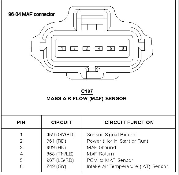
Take a look at the applies to: Here is a video on how you can test your maf sensor using a basic $5 multimeter. This is a non intake air temp iat sensor maf sensor. Need wiring diagram for the maf/iat 6 pin connector!!! Come join the discussion about performance, builds, modifications, reviews, engine swaps, classifieds, troubleshooting, maintenance, and more!
2003 Mustang Gt Maf Wiring Mustangforums Com from mustangforums.com If the maf sensor has 6 wires then this is a dead giveaway that it has the air temp sensor integrated inside. The most tedious job is to make the wiring harness. But if you don't have a wiring diagram, you can still find your signal wire by measuring it. If not, the structure won't work as it ought to be. 1987 ford mustang wiring diagram wiring diagram blog wrg 1178 93 mustang 5 0 wiring harness 86 93 mustang 5 0 computer w harness and mass air flow ford 89 93 efi mustang 5 0 wiring harness main and injector carxtc stereo wire harness oem fits ford mustang 1993 1999 ron francis wiring extended mustang 5 0l o2 sensor harness 87 93 auto fh 025e. A forum community dedicated to ford mustang owners and enthusiasts. I have put a 4.0l throttle body on and have the entire air box with maf, what i want to know is where i can locate the wiring diagram so i can wire the 4.0 maf sensor terminal into my 3.0 harness. * check the voltage of the maf sensor (refer to a repair manual for vehicle specific information).
Ford fiesta central locking wiring diagram 2018 mk6 pdf cigarette lighter mk5 st forum 2002 engine and transmission page 3 electrical 2011 free headlight 5th generation car diagrams owners manual puma speaker work 2008 service repair 02 08 haynes bentley radio mexican tdci volkswagen gti leather seats into a zetec transit kuga toyota.
Come join the discussion about performance, builds, modifications, reviews, engine swaps, classifieds, troubleshooting, maintenance, and more! Save your money, the chip is a ohm resistor at radio shack for under $2.00. Learn how this device is connected to the ecm and vehicle electronics in general. If not, the structure won't work as it ought to be. Without knowing how much air is really getting into the engine, p0102 will be thrown. It splices in to you iat wire harness located at the intake tube between the air filter housing and throttle body. In addition to the sequential injector wiring, the connector for the mass air flow (maf) sensor needs to be wired into the harness. Take a look at the applies to: Each component should be placed and linked to different parts in particular manner. 1987 ford mustang wiring diagram wiring diagram blog wrg 1178 93 mustang 5 0 wiring harness 86 93 mustang 5 0 computer w harness and mass air flow ford 89 93 efi mustang 5 0 wiring harness main and injector carxtc stereo wire harness oem fits ford mustang 1993 1999 ron francis wiring extended mustang 5 0l o2 sensor harness 87 93 auto fh 025e. To figure out what's going on, i need a circuit diagram (schematic) of the maf/iat unit. First i had to strip the entire harness from the 1989 f150, clean it and make sure all the connectors matched. Box on the right column to check for specific application info.
Here is a video on how you can test your maf sensor using a basic $5 multimeter. Published by ford motor company ltd/ford werke ag. When we study the wiring diagram, some more unusual aspects become visible. Take a look at the applies to: If not, the structure won't work as it ought to be.
Need 2008 Ford Fusion Maf Iat Wiring Diagram from www.justanswer.com Each part ought to be placed and connected with different parts in particular way. Save your money, the chip is a ohm resistor at radio shack for under $2.00. Each component should be placed and linked to different parts in particular manner. Ford fiesta work manual 2002 2008 free factory service. Need to find iat/maf sensor diagram for 2003 ford ranger. Ford fiesta central locking wiring diagram 2018 mk6 pdf cigarette lighter mk5 st forum 2002 engine and transmission page 3 electrical 2011 free headlight 5th generation car diagrams owners manual puma speaker work 2008 service repair 02 08 haynes bentley radio mexican tdci volkswagen gti leather seats into a zetec transit kuga toyota. The lt blured wire outputs the maf signal to the pcm. I have put a 4.0l throttle body on and have the entire air box with maf, what i want to know is where i can locate the wiring diagram so i can wire the 4.0 maf sensor terminal into my 3.0 harness.
Testing the maf (mass air flow) sensor on your ford truck or suv or full size van is a very simple and easy affair.this article will walk you through the whole process without removing the maf sensor from the engine.
Each part ought to be placed and connected with different parts in particular way. To figure out what's going on, i need a circuit diagram (schematic) of the maf/iat unit. It splices in to you iat wire harness located at the intake tube between the air filter housing and throttle body. Each component should be placed and linked to different parts in particular manner. A forum community dedicated to ford mustang owners and enthusiasts. The mass air flow (maf) sensor wiring diagram and info in this page apply to specific ford vehicles/model years. Box on the right column to check for specific application info. Learn how this device is connected to the ecm and vehicle electronics in general. In addition to the sequential injector wiring, the connector for the mass air flow (maf) sensor needs to be wired into the harness. Start by inspecting the wiring. I have a haynes book for the focus, but the engine controls circuit diagram it contains is ambiguous. * check the voltage of the maf sensor (refer to a repair manual for vehicle specific information). 1987 ford mustang wiring diagram wiring diagram blog wrg 1178 93 mustang 5 0 wiring harness 86 93 mustang 5 0 computer w harness and mass air flow ford 89 93 efi mustang 5 0 wiring harness main and injector carxtc stereo wire harness oem fits ford mustang 1993 1999 ron francis wiring extended mustang 5 0l o2 sensor harness 87 93 auto fh 025e.
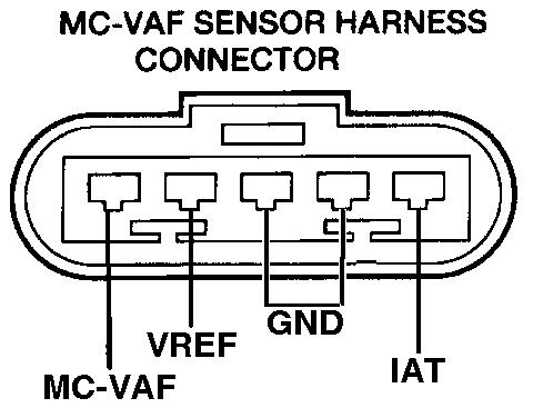
* unplug and reconnect the maf wiring harness a few times to clear the contacts. Describe and identify the diagram component q. Testing the maf (mass air flow) sensor on your ford truck or suv or full size van is a very simple and easy affair.this article will walk you through the whole process without removing the maf sensor from the engine. I need to know which wires connect to the maf and the iat in the maf/iat module, and i need to know which (color) wires go where to get to ground and the pcm. Describe and identify the diagram component t.
Diypnp Documentation For 1993 1994 Ford Probe from www.diyautotune.com One will by 5 volts, which powers the device and is supplied by the ecu. Problem with this system is, that you can not adjust anything and have to run a constant. All you need is a multimeter. I have put a 4.0l throttle body on and have the entire air box with maf, what i want to know is where i can locate the wiring diagram so i can wire the 4.0 maf sensor terminal into my 3.0 harness. Maf wiring i am doing one of the intake mods i found on this forum and just have one question. Describe and identify the diagram component t. * check the voltage of the maf sensor (refer to a repair manual for vehicle specific information). Ok, if all of the above check out ok, then your next step is to make check the continuity of the maf sensor's wires between the pcm connector and the maf sensor's connector.
They should be used as a reference for earier fi models as for wire colors could have changed this thread is closed due to more diagrams are to follow i am the original.
Start by inspecting the wiring. A forum community dedicated to ford mustang owners and enthusiasts. Mazda wiring diagrams worksheet #1 1. They should be used as a reference for earier fi models as for wire colors could have changed this thread is closed due to more diagrams are to follow i am the original. * unplug and reconnect the maf wiring harness a few times to clear the contacts. Installing chip and want to double check wiring. I need to know which wires connect to the maf and the iat in the maf/iat module, and i need to know which (color) wires go where to get to ground and the pcm. 1987 ford mustang wiring diagram wiring diagram blog wrg 1178 93 mustang 5 0 wiring harness 86 93 mustang 5 0 computer w harness and mass air flow ford 89 93 efi mustang 5 0 wiring harness main and injector carxtc stereo wire harness oem fits ford mustang 1993 1999 ron francis wiring extended mustang 5 0l o2 sensor harness 87 93 auto fh 025e. Need wiring diagram for the maf/iat 6 pin connector!!! Here is a video on how you can test your maf sensor using a basic $5 multimeter. This is a non intake air temp iat sensor maf sensor. Ford fiesta work manual 2002 2008 free factory service. If not, the structure won't work as it ought to be.