T1 Crossover Cable Diagram : Make T1 Crossover Cable Cables And Connectors : For instance, you need cross cable if you are connecting.. Usually this is the case when an isdn line is provided from a phone system. The wire that is crimped to pin 2 at one end is attached to pin 6 at the other end and the pins 3 and 6 wires go to pins 1 and 2 respectively in the other connector. If you need a crossover cable, and have a few extra standard ethernet cables around your place, you do not need to go out and buy a separate cable. A crossover cable does exactly as its name suggests, it crosses over the wire from pin 1 at one end to pin 3 at the other connector. Updated on april 23, 2020 doc navigation ← add service dependencies compile for a 64 bit os (for legacy versions prior to march 2010).
For instance, you need cross cable if you are connecting. Below i show you what the connectors for each type of cross over would look like is using the full 4 pairs. Look for a crossover cable color code with a wiring diagram for rj45 crossover cable or cross cable is a type of ethernet cable that is used to connect similar types of networking devices, in contrast to straight through cable which is used to connect different devices. If you need a crossover cable, and have a few extra standard ethernet cables around your place, you do not need to go out and buy a separate cable. The american national standards institute ( ansi ) states in ansi.
Crossover T1 Cable Voip Info from www.voip-info.org An ethernet crossover cable is a crossover cable for ethernet used to connect computing devices together directly. Updated on april 23, 2020 doc navigation ← add service dependencies compile for a 64 bit os (for legacy versions prior to march 2010). A crossover cable does exactly as its name suggests, it crosses over the wire from pin 1 at one end to pin 3 at the other connector. T1e1j1 schematron.org t1 cables use four wires: The below diagram is not quite correct. Get it as soon as fri, may 21. Two computers (via their network interface controllers) or two switches to each other.by contrast, straight through patch cables are used to connect devices of different types, such as a computer to a network switch. See our website for more information at:
For the physical cable connection it is necessary to use a t1 crossover cable.
Two individually shielded, 22awg, 100ohm pairs, maximize the performance of your expensive t1 circuits and equipment. If you need a crossover cable, and have a few extra standard ethernet cables around your place, you do not need to go out and buy a separate cable. You can send up to 4 telephone lines on one 4 pair cable that. Below i show you what the connectors for each type of cross over would look like is using the full 4 pairs. Using standard twisted pair cable and rj45 ends, make the following connections: Look for a crossover cable color code with a wiring diagram for rj45 crossover cable or cross cable is a type of ethernet cable that is used to connect similar types of networking devices, in contrast to straight through cable which is used to connect different devices. For the physical cable connection it is necessary to use a t1 crossover cable. Updated on april 23, 2020 doc navigation ← add service dependencies compile for a 64 bit os (for legacy versions prior to march 2010). In this case, the cabling between the bri port rj45 socket and the isdn nt1 would be a straight through (1 to 1) category 5 cable. Diagram for building a t1 crossover cable. Pin 1 to pin 4 pin 2 to pin 5. One end t568a, other end t568b (crossover cable). Get it as soon as fri, may 21.
You need the rj45 connectors to connect the wires due to physical resemblance. For instance, you need cross cable if you are connecting. The below diagram is not quite correct. In this case, the cabling between the bri port rj45 socket and the isdn nt1 would be a straight through (1 to 1) category 5 cable. A crossover cable does exactly as its name suggests, it crosses over the wire from pin 1 at one end to pin 3 at the other connector.
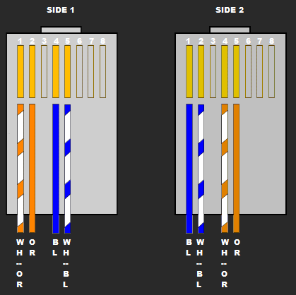
How To Make A T1 Crossover Cable Free Ccna Workbook from www.freeccnaworkbook.com Pin 1 to 4, 2 to 5, 4 to 1 and 5 to 2. The below diagram is not quite correct. Two computers (via their network interface controllers) or two switches to each other.by contrast, straight through patch cables are used to connect devices of different types, such as a computer to a network switch. In this case, the cabling between the bri port rj45 socket and the isdn nt1 would be a straight through (1 to 1) category 5 cable. See our website for more information at: The below diagram is not quite correct. An ethernet crossover cable is a crossover cable for ethernet used to connect computing devices together directly. Because a t1 uses pins 1,2,4,5 and a cat5 cable uses pins 1,2,3,6.
So in this diagram we can see that pin 1 is connecting to pin 4 and pin 2 is connecting to pin 5.
Pin 1 to 4, 2 to 5, 4 to 1 and 5 to 2. In this case, the cabling between the bri port rj45 socket and the isdn nt1 would be a straight through (1 to 1) category 5 cable. Usually this is the case when an isdn line is provided from a phone system. With a few minutes work, you can splice your own crossover cable without the need of the tools that other guides say that you absolutely need. See our website for more information at: A crossover cable does exactly as its name suggests, it crosses over the wire from pin 1 at one end to pin 3 at the other connector. T1/e1/j1 rj48 cable diagram the following illustration provides the wiring connections for straight or crossover cables. Get it as soon as fri, may 21. Pin 1 to pin 4 pin 2 to pin 5. If you take a 568b ethernet cable its the orange pair and blue pair. Diagram for building a t1 crossover cable. On a 568a cable it's the green pair and blue pair. Below i show you what the connectors for each type of cross over would look like is using the full 4 pairs.
Free shipping on orders over $25 shipped by amazon. The below diagram is not quite correct. Two for the transmit signal and two for the receive. Diagram for building a t1 crossover cable. You can send up to 4 telephone lines on one 4 pair cable that.
Network Wiring How To Fryguy S Blog from i2.wp.com One end t568a, other end t568b (crossover cable). Two individually shielded, 22awg, 100ohm pairs, maximize the performance of your expensive t1 circuits and equipment. Usb to rca cord splice wiring diagram audio. Diagram for building a t1 crossover cable. Using standard twisted pair cable and rj45 ends, make the following connections: If you take a 568b ethernet cable its the orange pair and blue pair. Look for a crossover cable color code with a wiring diagram for rj45 crossover cable or cross cable is a type of ethernet cable that is used to connect similar types of networking devices, in contrast to straight through cable which is used to connect different devices. Pin 1 to 4, 2 to 5, 4 to 1 and 5 to 2.
Updated on april 23, 2020 doc navigation ← add service dependencies compile for a 64 bit os (for legacy versions prior to march 2010).
T1/e1/j1 rj48 cable diagram the following illustration provides the wiring connections for straight or crossover cables. Although shielded t1 cable is the ideal, you will find that using a category 5 (cat5) patch cable will work just fine with out any issues. You need the rj45 connectors to connect the wires due to physical resemblance. For instance, you need cross cable if you are connecting. T1e1j1 schematron.org t1 cables use four wires: In this case, the cabling between the bri port rj45 socket and the isdn nt1 would be a straight through (1 to 1) category 5 cable. Diagram for building a t1 crossover cable. To make a t1 crossover cable you will need an rj45 crimping tool and at least one rj45 end. Free shipping on orders over $25 shipped by amazon. Pin 1 to 4, 2 to 5, 4 to 1 and 5 to 2. If you take a 568b ethernet cable its the orange pair and blue pair. From the thousand photographs on the internet about t1 wiring diagram rj45, we choices the very best choices using ideal image resolution only for you, and now this pictures is among images libraries in our finest images gallery with regards to t1 wiring diagram rj45.lets hope you can enjoy it. So in this diagram we can see that pin 1 is connecting to pin 4 and pin 2 is connecting to pin 5.