Home
› Wiring Electric Brakes : Trailer Brake Control Wiring Diagram | Trailer Wiring Diagram / This type of connector is excellent for consumer trailers.
Wiring Electric Brakes : Trailer Brake Control Wiring Diagram | Trailer Wiring Diagram / This type of connector is excellent for consumer trailers.
Wiring Electric Brakes : Trailer Brake Control Wiring Diagram | Trailer Wiring Diagram / This type of connector is excellent for consumer trailers.. Electric brake systems consist of components mounted both on the tow vehicle and the trailer. There are wires extending from the switch and using a circuit tester, you can find the wire that has power when the brake pedal is pressed. You may have to cut into the trailer wiring's sheathing to find the wire. You should be getting at maximum: One wire is for 12 volt power to the brake magnets and the other wire should be grounded either to the trailer frame or to the main trailer ground wire.
This type of connector is excellent for consumer trailers. Curt 51323 quick plug electric trailer brake controller wiring harness, select ford, land rover, lincoln, mercury trucks and suvs. Ensure it is sealed off and cannot create a short circuit with any other wire or the chassis. It reveals the parts of the circuit as streamlined forms, as well as the power and signal connections in between the gadgets. Connect the breakaway switch's other lead to the blue wire with a scotchlok connector.
1995 wells cargo wiring diagram trailer brakes? - Fixya from www.fixya.com Electric brake systems consist of components mounted both on the tow vehicle and the trailer. This 7 pin trailer wiring diagram electric brakes model is more suitable for sophisticated trailers and rvs. It ought not be carrying significant loads through the trip. The red (stoplight) wire must be connected to the cold side of the brake pedal stoplight switch. It also talks about electric brake controller.thanks for watching ! For these systems to operate properly, the trailer wiring end plug on the trailer must match the wiring pattern of the mating plug on the tow vehicle. The service brake circuit must be disconnected from an existing trailer plug. If your vehicle comes with a towing package you should have a brake control plug already wired and ready to go.
A wiring diagram is a streamlined conventional pictorial representation of an electric circuit.
It does not matter which wire is used for power or ground because they are not polarized. For these systems to operate properly, the trailer wiring end plug on the trailer must match the wiring pattern of the mating plug on the tow vehicle. Is the electric brake wiring connected to the pin or plug that i plug in to the back of my vehicle for brake and turning signal lights or is there a completely separate wire system that i need for the electric brakes ? When comparing wire thickness, a smaller gauge number represents a thicker wire. If not, the arrangement will not function as it ought to be. Connect your blue wire (which is the one that controls brakes) to the multimeter with an ammeter setting between the brake controller and trailer connector. Hi, i'm about to wire up the new brakes and i see that there are two wires per brake. Coming out of my 7 pin connector i have a light blue, a yellow, and a black wire that are unused. It ought not be carrying significant loads through the trip. For decades, hooking up trailer lights and electric brakes on most cars meant splicing into the wiring harness near the back bumper and just adding the extra load of trailer lights and brakes to the car's electrical system. You should be getting at maximum: One wire is for 12 volt power to the brake magnets and the other wire should be grounded either to the trailer frame or to the main trailer ground wire. Curt 51323 quick plug electric trailer brake controller wiring harness, select ford, land rover, lincoln, mercury trucks and suvs.
The blue (brake output) wire must be connected to the trailer connector's brake wire. 4.7 out of 5 stars. You can find a decent circuit tester on amazon.com for around $20, or just shop around for what you want. It also talks about electric brake controller.thanks for watching ! The brake controller comes with a wiring harness that is the kind you have to splice into your vehicle's wiring.
Wiring Electric Trailer Brakes Diagram | Trailer Wiring Diagram from trailer-wiring-diagram.com Refer to the diagram below to locate yours. On # 90885, the white wire grounds to the negative battery terminal. The brake controller comes with a wiring harness that is the kind you have to splice into your vehicle's wiring. It reveals the parts of the circuit as streamlined forms, as well as the power and signal connections in between the gadgets. Wiring up the electric brakes wiring up the electric brakes. There is a very basic wiring electric trailer brakes diagram. Brake blue 18 12 electric brake control, power for brakes break away switch battery red (or black) 12 fuse block or fused battery lead break away kit, interior lights and battery charger. Connect the breakaway switch's other lead to the blue wire with a scotchlok connector.
The blue (brake output) wire must be connected to the trailer connector's brake wire.
One end of the wiring harness plugs into the vehicle's factory harness under the dash, and the other end plugs into the brake controller. Do not disturb the position of the switch. There is a very basic wiring electric trailer brakes diagram. Back up purple 16 back up of vehicle's wiring harness back up lights (if available) / hydraulic coupler. To make wiring a brake controller easy and cost efficient we sell a brake controller wiring kit that does both 20amp and 30amp scenarios. The brake controller comes with a wiring harness that is the kind you have to splice into your vehicle's wiring. Connect the breakaway switch's other lead to the blue wire with a scotchlok connector. For decades, hooking up trailer lights and electric brakes on most cars meant splicing into the wiring harness near the back bumper and just adding the extra load of trailer lights and brakes to the car's electrical system. It ought not be carrying significant loads through the trip. It also talks about electric brake controller.thanks for watching ! Curt 51323 quick plug electric trailer brake controller wiring harness, select ford, land rover, lincoln, mercury trucks and suvs. On # 90885, the white wire grounds to the negative battery terminal. The service brake circuit must be disconnected from an existing trailer plug.
It reveals the parts of the circuit as streamlined forms, as well as the power and signal connections in between the gadgets. Blue = electric brakes or hydraulic reverse disable (see blue wire notes below.) in the trailer wiring diagram and connector application chart below, use the first 5 pins, and ignore the rest. Connect the breakaway switch's other lead to the blue wire with a scotchlok connector. The red (stoplight) wire must be connected to the cold side of the brake pedal stoplight switch. You may have to cut into the trailer wiring's sheathing to find the wire.
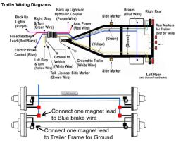
Dual Axle Trailer Brake Wiring Diagram - Collection - Wiring Diagram Sample from images.etrailer.com Is the electric brake wiring connected to the pin or plug that i plug in to the back of my vehicle for brake and turning signal lights or is there a completely separate wire system that i need for the electric brakes ? One end of the wiring harness plugs into the vehicle's factory harness under the dash, and the other end plugs into the brake controller. If not, the arrangement will not function as it ought to be. For these systems to operate properly, the trailer wiring end plug on the trailer must match the wiring pattern of the mating plug on the tow vehicle. Elecbrakes must be connected to trailer wiring circuits as outlined in the wiring diagram. Electric brake systems consist of components mounted both on the tow vehicle and the trailer. This short video is about trailer brakes, electric brakes and wiring. Each component ought to be set and connected with different parts in particular manner.
One wire is for 12 volt power to the brake magnets and the other wire should be grounded either to the trailer frame or to the main trailer ground wire.
There are wires extending from the switch and using a circuit tester, you can find the wire that has power when the brake pedal is pressed. You may have to cut into the trailer wiring's sheathing to find the wire. 4.7 out of 5 stars. Best selection & value on auto parts, accessories & tools at amazon. Wiring up the electric brakes wiring up the electric brakes. The black wire is the power supply line to the brake control. White pin to your floor. If your vehicle comes with a towing package you should have a brake control plug already wired and ready to go. For these systems to operate properly, the trailer wiring end plug on the trailer must match the wiring pattern of the mating plug on the tow vehicle. The blue (brake output) wire must be connected to the trailer connector's brake wire. It also talks about electric brake controller.thanks for watching ! This 7 pin trailer wiring diagram electric brakes model is more suitable for sophisticated trailers and rvs. The location of your vehicle's factory wiring harness may vary.