Rv Trailer Plug Wiring Diagram / Common Rv Power Connectors : Above we have describes the main types of trailer wiring diagrams.. If not, the arrangement will not function as it ought to be. As a professional rv transporter i have seen to many trucks wired with those 2 wires to small and cause a fire from overheating. 4 & 5 way flat connector wiring diagrams. A wiring diagram is a streamlined traditional photographic depiction of an electric circuit. Need to know which color wire go to which post.
These types of outlets are usually marked travel trailer use only and will give you about 3,600 watts of power: Some of the wiring systems used for connecting a tow vehicle with a toad (or towed vehicle) are simpler than others, but there are standards for all of the connectors and how they are wired. If not, the arrangement will not function as it ought to be. Collection of travel trailer wiring schematic. Use the rv electrical diagram we made below to get an understanding of what powers what and to learn how an rv electrical system works.
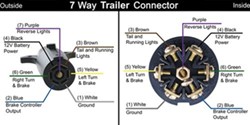
7 Way Rv Trailer Connector Wiring Diagram Etrailer Com from images.etrailer.com The image above shows a single axle trailer, and the next image shows wiring for tandem axles. Only the (blue) brake and (white) ground wires are different. 4 pin trailer wiring diagram. Above we have describes the main types of trailer wiring diagrams. 4 & 5 way flat connector wiring diagrams. A wiring diagram is a streamlined traditional photographic depiction of an electric circuit. These types of outlets are usually marked travel trailer use only and will give you about 3,600 watts of power: Use this handy trailer wiring diagram for a quick reference for various electrical connections for trailers.
But, it doesn't have as sophisticated and electric consuming attributes that rv and other expensive trailers might have.
Wiring plug diagram created date: Typical trailer wiring diagram and schematic these 2 wire diagrams fit the needs of most trailers. Trailer wiring diagrams trailer wiring connectors various connectors are available from four to seven pins that allow for the transfer of power for the lighting as well as auxiliary functions such as an electric trailer brake controller, backup lights, or a 12v power supply for a winch or interior trailer lights. 120 volts x 30 amps = 3,600 watts. Wiring diagram for ifor williams trailer lights best ifor. A wiring diagram is a streamlined traditional photographic depiction of an electric circuit. Use the rv electrical diagram we made below to get an understanding of what powers what and to learn how an rv electrical system works. The image above shows a single axle trailer, and the next image shows wiring for tandem axles. Only the (blue) brake and (white) ground wires are different. This fleetwood wilderness travel trailer wiring diagram model is much more appropriate for sophisticated trailers and rvs. White pin for the floor. 4 & 5 way flat connector wiring diagrams. If not, the arrangement will not function as it ought to be.
The image above shows a single axle trailer, and the next image shows wiring for tandem axles. Collection of travel trailer wiring schematic. Rv electrical diagram (wiring schematic) understanding you campers electrical wiring can be very confusing. Only the (blue) brake and (white) ground wires are different. How to test 7 way trailer rv electrical plugin this video i show how to test a 7 way trailer plug wiring harness for towing a travel trailer or rv by using a.
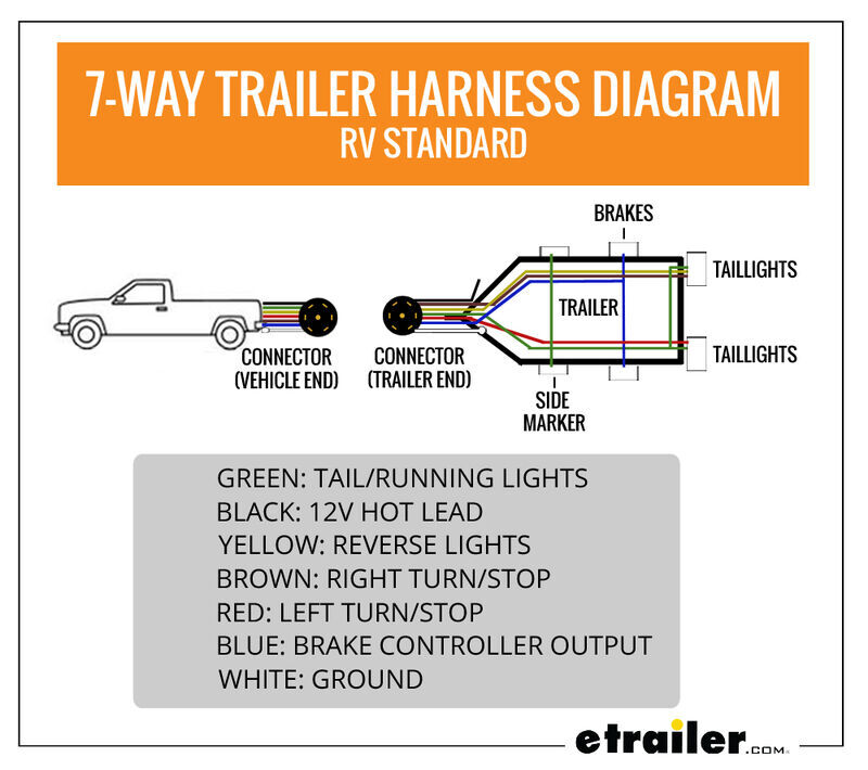
Wiring Trailer Lights With A 7 Way Plug It S Easier Than You Think Etrailer Com from www.etrailer.com 6 way plug wiring diagr am standard wiring* post purpose wire color tm park lights brown gd ground black (or white) s trailer brakes blue lt left turn/brake light yellow rt right turn/brake light green a accessory red the most common variances on this diagram will be the (blue/brake) & (red/acc.) wires will be inverted. Wiring plug diagram created date: Rv electrical diagram (wiring schematic) understanding you campers electrical wiring can be very confusing. 120 volts x 30 amps = 3,600 watts. Most new vehicles equipped with a tow package have connectors. When wiring a trailer connector, it is best to wire by function, as wire colors can vary. Collection of travel trailer wiring schematic. Below is the generic schematic of how the wiring goes.
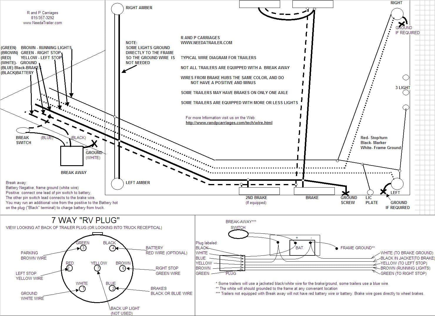
Plug body •ensure any power sources are disconnected •loosen face setscrew and cable clamp •slide plug body back onto trailer wiring, exposing terminals on back of plug face •wiring schematics above are looking at the rear of the plug face, with the setscrew at the 12 o'clock position •secure wiring in terminal clamps, ensuring that.
4 pin trailer wiring diagram. As a professional rv transporter i have seen to many trucks wired with those 2 wires to small and cause a fire from overheating. Below is the generic schematic of how the wiring goes. Use the rv electrical diagram we made below to get an understanding of what powers what and to learn how an rv electrical system works. 120 volts x 30 amps = 3,600 watts. A wiring diagram is a streamlined traditional photographic depiction of an electric circuit. Car trailer wiring diagram uk new best ford 7 way trailer plug. When wiring a trailer connector, it is best to wire by function, as wire colors can vary. Each component ought to be set and connected with different parts in particular manner. It reveals the parts of the circuit as streamlined shapes, as well as the power and also signal links in between the gadgets. The image above shows a single axle trailer, and the next image shows wiring for tandem axles. Collection of travel trailer wiring schematic. 6 way plug wiring diagr am standard wiring* post purpose wire color tm park lights brown gd ground black (or white) s trailer brakes blue lt left turn/brake light yellow rt right turn/brake light green a accessory red the most common variances on this diagram will be the (blue/brake) & (red/acc.) wires will be inverted.
It gets complicated when you have trailers with more cables, and in this case, you need an adapter to make the connections. It reveals the parts of the circuit as streamlined shapes, as well as the power and also signal links in between the gadgets. Plug body •ensure any power sources are disconnected •loosen face setscrew and cable clamp •slide plug body back onto trailer wiring, exposing terminals on back of plug face •wiring schematics above are looking at the rear of the plug face, with the setscrew at the 12 o'clock position •secure wiring in terminal clamps, ensuring that. 4 & 5 way flat connector wiring diagrams. Wiring diagram for ifor williams trailer lights best ifor.
7 Way Plug Information R And P Carriages Cargo Utility Dump Equipment Car Haulers And Enclosed Trailers In Chicago Ottawa Dekalb And Joliet Il from dealer-cdn.com Trailer side car side wiring plug diagram. Trailer wiring diagrams trailer wiring connectors various connectors are available from four to seven pins that allow for the transfer of power for the lighting as well as auxiliary functions such as an electric trailer brake controller, backup lights, or a 12v power supply for a winch or interior trailer lights. Collection of travel trailer wiring schematic. 4 pin trailer wiring diagram. If your vehicle is not equipped with a working trailer wiring harness, there are a number of different solutions to provide the perfect fit for. Each component ought to be set and connected with different parts in particular manner. 4 & 5 way flat connector wiring diagrams. Plug body •ensure any power sources are disconnected •loosen face setscrew and cable clamp •slide plug body back onto trailer wiring, exposing terminals on back of plug face •wiring schematics above are looking at the rear of the plug face, with the setscrew at the 12 o'clock position •secure wiring in terminal clamps, ensuring that.
How to test 7 way trailer rv electrical plugin this video i show how to test a 7 way trailer plug wiring harness for towing a travel trailer or rv by using a.
When wiring a trailer connector, it is best to wire by function, as wire colors can vary. Trailer side car side wiring plug diagram. If your vehicle is not equipped with a working trailer wiring harness, there are a number of different solutions to provide the perfect fit for. Wiring plug diagram created date: Most new vehicles equipped with a tow package have connectors. Trailer wiring diagrams trailer wiring connectors various connectors are available from four to seven pins that allow for the transfer of power for the lighting as well as auxiliary functions such as an electric trailer brake controller, backup lights, or a 12v power supply for a winch or interior trailer lights. Typical trailer wiring diagram and schematic these 2 wire diagrams fit the needs of most trailers. 6 way plug wiring diagr am standard wiring* post purpose wire color tm park lights brown gd ground black (or white) s trailer brakes blue lt left turn/brake light yellow rt right turn/brake light green a accessory red the most common variances on this diagram will be the (blue/brake) & (red/acc.) wires will be inverted. Below is the generic schematic of how the wiring goes. This fleetwood wilderness travel trailer wiring diagram model is much more appropriate for sophisticated trailers and rvs. But, it doesn't have as sophisticated and electric consuming attributes that rv and other expensive trailers might have. Each component ought to be set and connected with different parts in particular manner. These types of outlets are usually marked travel trailer use only and will give you about 3,600 watts of power: